Table of Contents
Advertisement
Available languages
Available languages
Quick Links
Advertisement
Chapters
Table of Contents

Related Manuals for Occhio Piu alto 3d NV

Summary of Contents for Occhio Piu alto 3d NV
- Page 1 Più alto 3d NV Montageanleitung mounting instructions flat plug track...
- Page 3 Più alto 3d NV Montageanleitung S. 2 mounting instructions p. 51 flat plug track...
-
Page 5: Table Of Contents
Inhalt Sicherheitshinweise Produktbeschreibung Montage head Installation Informationen Technische Daten... -
Page 6: Sicherheitshinweise
Sicherheitshinweise Lesen Sie die Montage-/Gebrauchs- Allgemeine Sicherheitshinweise anweisung sorgfältig durch, bevor Sie die Leuchte installieren. Beach- ten Sie die Sicherheitshinweise in dieser Anleitung genau und Bewah- Die Montage von Elektrokompo- ren Sie die Anleitung auf. nenten darf nur von qualifiziertem Fachpersonal durchgeführt werden. Reparaturarbeiten dürfen nur Erklärung der Kennzeichnung von autorisiertem Fachpersonal oder dem Hersteller durchgeführt werden. Dieses Zeichen macht Sie auf eine Vor allen Arbeiten am Strahler gefährliche Situation aufmerksam, (Installation, Leuchtmittelwechsel, die eine schwere Verletzung oder Reinigung etc.) diesen unbedingt den Tod nach sich ziehen kann, vom Stromnetz trennen. wenn sie nicht beachtet wird. Es 0.2m macht Sie zudem auf mögliche Sachschäden und andere wichtige Informationen in Verbindung mit Sicherheitsabstand zu brennbaren diesem Produkt aufmerksam. Objekten einhalten: 20 cm! Dieses Zeichen macht Sie auf heiße Achtung: Die Oberfläche des Strah- Oberflächen aufmerksam, deren lers kann nach längerer Betriebs- Berührung Verbrennungen zur Folge dauer heiß sein! haben können. Vor allen Arbeiten am Strahler (Montage des Strahlers, Wechsel der Inserts, usw.), Strahler immer ausschalten und mindestens 30... -
Page 7: Produktbeschreibung
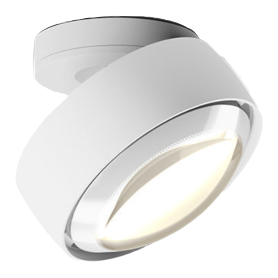
Produktbeschreibung Occhio Più alto 3d NV ist ein Aufbau- Die verschiedenen optischen Kom- strahler mit einzigartiger 3D-Kinematik ponenten (Inserts) können jederzeit für maximale Beweglichkeit. über einen einfachen Mechanismus Più alto 3d NV steht in den Montage- getauscht bzw. neu zusammengestellt varianten „up“... -
Page 9: Montage Head
Montage head... - Page 11 Montage head Aufbau Piu alto 3d head head Leuchtmittel Glas satiniert Glas soft edge, Reflektor Glas satiniert oder S 40/20/10 Farbfilter (optional) Glas soft edge oder Farbfilter Linse Farbfilter (optional) (optional) Blendschutzring Version B Version C Version S 40/20/10...
- Page 12 Leuchtmittel einsetzen Niedervolt Halogen Leuchtmittel (max. 60 W) in die Gy 6.35 Fassung des Strahlerkopfs einsetzen. Glaskolben des Leuchtmittels nur mit ei- nem weichen Tuch, nicht mit der bloßen Hand anfassen. Fingerabdrücke auf dem Leuchtmittel vor dem Einschalten der Leuchte mit einem weichen Tuch abwischen.
- Page 13 Kombinationen der Inserts Farbfilter / Glas satiniert spot S 40/20/10 / Glas soft edge Blend- schutzring Glas soft edge Farbfilter inside Glas satiniert Reflektor Leuchtmittel Leuchtmittel Glas soft edge / Linse spot S 40/20/10 / Farbfilter Blend- schutzring Farbfilter inside Linse Glas soft edge Reflektor Leuchtmittel Leuchtmittel Farbfilter / Linse Linse Farbfilter inside Leuchtmittel...
- Page 14 Reflektor einsetzen (nur bei S 40/20/10) Occhio-Tool (beiliegend) mit dem schmalen Ende in die Nut des Auslöse- stifts einführen. Occhio-Tool so weit drehen bis der Aus- lösestift nach oben springt. Gefederte Fassung des Leuchtmittels etwas nach oben halten und gleichzeitig …...
- Page 15 Montage head … spot-Reflektor mit der seitlichen Öffnung vorsichtig über das Leucht- mittel und die Fassung schieben. spot-Reflektor mit dem Rand in beide Federn einfügen und gegen die Federn drücken. In dieser Position den Rand des spot- Reflektors in die Kerbe des Auslöse- stifts klemmen.
- Page 16 Inserts einsetzen Occhio-Tool (beiliegend) mit dem schmalen Ende in die Nut des Auslöse- stifts einführen. Occhio-Tool so weit drehen bis der Aus- lösestift nach oben springt. Inserts mit dem Rand in beide Federn einfügen und gegen die Federn drücken.
- Page 17 Kerbe des Auslösestifts klemmen. Auslösestift bündig eindrücken. Er rastet in Endposition ein. Der head ist nun für die weitere Monta- ge vorbereitet. Inserts entnehmen: Auslösestift mit Occhio-Tool so weit drehen bis er nach oben springt. Inserts gegen die Federn drücken und entnehmen.
-
Page 19: Installation
Installation Più 3d up für feste Decke Più 3d flat für Hohlraum-/Einputzdose Più 3d plug für Hohldecke mit Einputzplatte Più 3d track für 1- oder 3-Phasenschiene... - Page 20 Installation...
- Page 21 Più 3d up Bohrungen/Dübel 230V AC Netzanschlussleitung Montageplatte mit Trafo und Anschlussklemmen Schrauben Inbusschrauben cover head...
- Page 22 Installation Beide transparente Klemmleisten von der Grundplatte lösen und abheben. Obere Klemmleiste nach hinten über den Trafo klappen. Untere Klemmleiste etwas herauszie- hen, so dass das Langloch zur Montage zugänglich wird.
- Page 23 Più 3d up Enden des Netzkabels auf 60 mm ablängen. Die Kabelenden 10 mm abisolieren. Die Erdungsleitung wird nicht benötigt. 230V AC Netzanschlussleitung 60 mm 10 mm Netzanschlussleitung durch die Ausspa- rung der Montageplatte führen. 230V AC Montageplatte so drehen, dass die Netzanschlussleitung Löcher die gewünschte Ausrichtung haben.
- Page 24 Installation Zwei Löcher ø 6 mm bohren, Dübel bündig einsetzen und Montageplatte anschrauben (Schrauben und Dübel sind im Lieferumfang enthalten). Untere Klemmleiste (Primäranschluss) wieder in die Montageplatte einrasten. click!
- Page 25 Più 3d up Netzkabel nach Schema fachgerecht an die zwei Klemmen des 230V Eingangs (gekennzeichnet mit PRI) anschließen. Obere Klemmleiste auf die untere Klemmleiste zurückklappen und bündig einrasten. click!
- Page 26 Installation Zur Vereinfachung der Montage, Leuch- te mit der beiliegenden langen Schraube befestigen. Schraube dazu mit der Hand bis zum Anschlag eindrehen und Leuchte zur Seite schwenken. Leuchtenkabel an die Klemmen der Sekundärseite des Trafos (gekennzeich- net mit SEC) anschließen.
- Page 27 Più 3d up Kabel in die Aussparung der Klemmleis- te legen. Lange Schraube wieder entfernen. Leuchtenkörper mit mitgelieferten Schrauben (Inbus) auf beide Abstands- halter der Montageplatte schrauben. Dabei darauf achten, dass die Rastna- sen des Leuchtenkörpers (siehe Detail) bündig auf den Abstandshaltern auflie- gen und das Kabel nicht eingeklemmt wird.
- Page 28 Installation Cover vorsichtig über den Leuchten- arm führen und durch Rechtsdrehung click! arretieren. Kratzschutz von cover und Leuchten- arm entfernen. Die Leuchte ist nun fertig montiert.
- Page 29 Più 3d up Mit dem Occhio 3d Gelenk lässt sich der Strahler in beliebige Richtung bewegen. Beide Gelenke verfügen über einen Anschlag. 360° Achtung! 360° Die Oberfläche des Strahlers kann im Dauerbetrieb heiß werden.
- Page 30 Installation...
- Page 31 Più 3d flat 230V AC Netzanschlussleitung Trafo Hohlraumdose (bauseitig) 12 V Anschlusskabel mit Klemmen Montageplatte flach Schrauben (Hohlraumdose) Inbusschrauben cover head...
- Page 32 Installation Mitgeliefertes 12 V Anschlusskabel durch die Hohlraumdose führen. 12 V Anschluss- kabel Kabelenden des 12V Anschlusskabels nach Schema an den Trafo anschließen. Trafo nach Schema an die Netzleitung anschließen. Technische Hinweise des jeweiligen Trafo-Herstellers beachten 230 V 12 V Trafo Achtung! Vor der Montage alle stromführenden...
- Page 33 Più 3d flat Montageplatte an die Hohlraumdose schrauben. Dabei die Klemmen durch die Öffnung führen. Darauf achten, dass die Schrauben bündig mit der Montageplatte abschlie- ßen. Kabelenden der Leuchte wie in der Ab- bildung an die Klemmen anschließen.
- Page 34 Installation Kabel mit Klemmen soweit wie möglich durch das Loch in die Hohlraumdose zurückschieben. Leuchtenkörper mit mitgelieferten Schrauben (Inbus) auf die Montageplat- te schrauben. Kabel dabei nicht einklemmen! Cover vorsichtig über den Leuchten- arm führen und durch Rechtsdrehung arretieren. click! Kratzschutz von cover und Leuchten- arm entfernen.
- Page 35 Più 3d flat Mit dem Occhio 3d Gelenk lässt sich der Strahler in beliebige Richtung bewegen. Beide Gelenke verfügen über einen Anschlag. 360° 360° Achtung! Die Oberfläche des Strahlers kann im Dauerbetrieb heiß werden.
- Page 36 Installation...
- Page 37 Più 3d plug 230V AC Netzanschlussleitung Anschlussleitung Trafo mit Klemmen Ausschnitt: > 196 x 196 mm Einputzplatte für rahmenlosen Einbau (Faserzementplatte mit Steckpunkt) 196 x 196 mm Dicke: 12,5 mm head mit plug...
- Page 38 Installation Deckenausschnitt im Format > 196 x 196 mm herstellen. Die Stromführenden Kabel sind nach dem Einbau der Einputzplatte durch die Öffnung nicht mehr erreichbar. Deshalb ist ggf. eine Revisionsklap- pe an anderer Stelle vorzusehen. Stromleitungen sind vor Einbau der > 196 mm > 196 mm Einputzplatte zu verlegen und an die Öffnung der Einputzplatte heranzu- führen. Mitgelieferte 12V Anschlussleitung nach Schema an den Trafo anschließen. Trafo nach Schema an die Netzleitung anschließen. Technische Hinweise des jeweiligen Trafo-Herstellers beachten.
- Page 39 Più 3d plug Kabel mit Klemmen und Karabiner des Sicherheitsseils durch die Öffnung der Schutzkappe führen. Einputzplatte fachgerecht bündig in der Öffnung montieren. Dazu vorgesehene Bohrlöcher verwenden. Wird die Platte an anderen Stellen fixiert, vor dem Anschrauben vorbohren, um die Einputzplatte nicht zu beschädigen. Fugen verputzen und scheifen.
- Page 40 Installation Malerarbeiten ausführen. Dabei darauf achten, dass die Innensei- te des Steckpunkts nicht verschmutzt wird. Schutzkappe mithilfe eines Schrauben- drehers entfernen. Kabelenden und Sicherungsseil etwas herausziehen. Sicherheitsschlaufe der Leuchte in den Karabiner einhängen!
- Page 41 Die Leuchte ist nun fertig montiert. Festen Halt der Leuchte überprüfen! Eine herabfallende Leuchte stellt eine erhebliche Gefahr dar! Mit dem Occhio 3d Gelenk lässt sich der Strahler in beliebige Richtung bewegen. Der Plug verfügt über keinen Anschlag. Das Gelenk am Leuchtenarm verfügt über einen Anschlag. 360°...
- Page 42 Installation...
- Page 43 Più 3d track EUTRAC-kompatible 1- oder 3-Phasen Stromschiene (230 V) 1- oder 3-Phasen Track-Adapter Gehäuse mit cover head inkl. Leuchtmittel und Inserts...
- Page 44 Installation Leuchtenarm wie in der Abb. ausrich- ten. Der Leuchtenkopf muss senkrecht nach unten zeigen. Cover kräftig nach unten ziehen (wird durch Magnetkraft gehalten). Track-Adapter am Gehäuse um 90° drehen. Achtung! Vor der Montage alle stromführenden Leitungen vom Stromnetz trennen!
- Page 45 Più 3d track Strahler an der gewünschten Stelle in die Schiene einsetzen. Unbeschrifteten Knebel um 90° im Uhr- zeigersinn schließen. Hiermit wird der Track-Adapter an den neutralen Leiter angeschlossen. Endposition des Knebels: parallel zur Schiene...
- Page 46 Installation Einstellen auf Phase 1 Einstellknebel um 90° im Uhrzeigersinn drehen. Der Track-Adapter ist nun an Phase 1 angeschlossen. Einstellen auf Phase 2 (nur 3- Phasen Track-Adapter) Einstellknebel um 90° gegen den Uhrzeigersinn drehen. Der Track-Adapter ist nun an Phase 2 angeschlossen.
- Page 47 Più 3d track Gehäuse um 90° schwenken. Ausrichtung: Parallel zur Stromschiene. Cover bündig zurückschieben (wird magnetisch gehalten). Schutzfolie von Gehäuse und body entfernen. Der Strahler ist nun fertig montiert.
- Page 48 Installation Mit dem Occhio 3d Gelenk lässt sich der Strahler in jede beliebige Richtung bewegen. Beide Gelenke verfügen über einen Anschlag. 360° 360° Achtung! Die Oberfläche des Strahlers kann im Dauerbetrieb heiß werden.
-
Page 50: Informationen
Pflegehinweise Leuch te nur in abgekühltem Zu stand reinigen! Zur Reinigung der Leuchte ein trocke- nes Mikrofasertuch oder das Occhio Reinigungsmittel verwenden. Info & Kontakt Weitere Fragen beantwortet gerne Ihr Occhio Fachhändler. www.occhio.com info@occhio.com... -
Page 51: Technische Daten
Technische Daten Leuchte Artikelbezeichnung Occhio Più alto 3d NV Più alto 3d up NV head ø 122 mm, für feste Decke base ø 88 mm, H 29 mm Gesamthöhe max. 189 mm Più alto 3d flat NV head ø 122 mm für Hohlraumdose... - Page 52 Technische Daten Leuchtmittel Leuchtmittelbezeichnung Niedervolt-Halogen Gy6.35 Hersteller OSRAM Herstellerbezeichnung HALOSTAR ECO Ausführung klar UV-Filter Abmessungen Leuchtmittel Länge: ca. 44 mm, ø12 mm Sockel Gy6.35 Betriebsspannung 12 V Lebensdauer 4000 h Farbtemperatur 3000 K Wirkungsgrad ~26 lm/W Energieeffizienzklasse – EEI Lichtstrom 1180 –...
- Page 53 Più alto 3d NV mounting instructions flat plug track...
- Page 55 Contents Safety precautions Product description Assembling the head Installation Information Technical data...
-
Page 56: Safety Precautions
Safety precautions Read through the mounting/use General safety precautions instructions carefully before install- ing the lamp. Follow the safety precautions in these instructions closely and keep the instructions in The assembly and installation of a safe place. electrical components must be car- ried out only by qualified personnel. Repairs must be carried out only by Explanation of symbols authorised, qualified personnel or the manufacturer. Before performing any work on the This symbol warns you of a danger- spotlight (installation, changing the ous situation which could lead to bulb, cleaning, etc.), it must be dis- serious injury or even death if the connected from the mains supply. instructions are not observed. It 0.2m also draws your attention to pos- sible material damage and provides other important information in con- Maintain the minimum safety nection with this product. distance from flammable materials: 20 cm. This symbol warns you of hot sur- faces, which could cause burns if Caution: When used for prolonged touched. periods, the surface of the spotlight can become hot. Before performing any work on the spotlight (fitting the spotlight, changing the insert, etc.), always switch the spot- light off and let it cool for at least 30... -
Page 57: Product Description
Product description Occhio Più alto 3d NV is a surface- At any time, the various optical compo- mounted spotlight with unique 3D nents (inserts) can be reconfigured or kinematics for maximum freedom of replaced using a simple mechanism. movement. Più alto 3d NV is available in the “up”... -
Page 59: Assembling The Head
Assembling the head... - Page 61 Assembling the head Configuration of the Più alto 3d head Head Bulb Satinised glass Soft-edge glass, Reflector satinised glass or S 40/20/10 colour filter (optional) Soft-edge glass or Colour filter Lens colour filter (optional) (optional) Anti-glare ring Version B Version C Version S 40/20/10...
- Page 62 Inserting the bulb Insert the low-voltage halogen bulb (max. 60 W) into the Gy 6.35 socket on the spotlight head. Always use a soft cloth when handling the bulb glass. Never touch it with bare hands. Use a soft cloth to wipe off any finger prints left on the bulb before switching the lamp on.
- Page 63 Insert combinations Colour filter/satinised glass S 40/20/10 spot/soft-edge glass Anti-glare ring Soft-edge glass Colour filter inside Satinised Reflector glass Bulb Bulb Soft-edge glass/lens S 40/20/10 spot/colour filter Anti-glare ring Colour filter inside Lens Soft-edge glass Reflector Bulb Bulb Colour filter/lens Lens Colour filter inside Bulb...
- Page 64 Inserting the reflector (for S 40/20/10 only) Insert the narrow end of the Occhio tool (supplied) into the groove of the release pin. Turn the Occhio tool until the release pin pops up. Lift the spring-mounted bulb socket slightly and hold it…...
- Page 65 Assembling the head …while at the same time carefully pushing the spot reflector over the bulb and socket through the side opening. Insert the edge of the spot reflector into the two springs and press against the springs. Holding it in this position, clip the edge of the spot reflector into the notch on the release pin.
- Page 66 Insert the narrow end of the Occhio tool (supplied) into the groove of the release pin. Turn the Occhio tool until the release pin pops up. Insert the edge of the inserts into the two springs and press against the...
- Page 67 Press the release pin in until it is flush. It clicks into its end position. The head is now ready for further as- sembly. To remove the inserts: Using the Occhio tool, turn the release pin until it pops up. Press the inserts against the springs and remove them.
-
Page 69: Installation
Installation Più 3d up for solid ceiling Più 3d flat for hollow ceiling/plastering box Più 3d plug for hollow ceiling with mounting board Più 3d track for 1- or 3-phase bus bar... - Page 70 Installation...
- Page 71 Più 3d up Drilled holes/rawlplugs 230 V AC mains cable Mounting plate with transformer and connecting terminals Screws Allen screws Cover Head...
- Page 72 Installation Release both transparent terminal strips from the base plate and lift them away. Fold the upper terminal strip backwards over the transformer. Pull the lower terminal strip out a little until the elongated mounting hole is accessible.
- Page 73 Più 3d up Cut the mains cable to a length of 60 mm. Strip 10 mm of insulation from the cable ends. The earth cable is not required. 230 V AC mains cable 60 mm 10 mm Guide the mains cable through the recess in the mounting plate.
- Page 74 Installation Drill two 6 mm diameter holes, push in the rawlplugs so that they lie flush and screw on the mounting plate (screws and rawlplugs are included in the scope of delivery). Snap the lower terminal strip (primary terminal) back into the mounting plate. Click!
- Page 75 Più 3d up Connect the mains cable to the two terminals of the 230 V input (marked with PRI) correctly in accordance with the diagram. Fold the upper terminal strip back onto the lower terminal strip and snap it into place so that it is flush.
- Page 76 Installation To simplify mounting, fasten the lamp with the long screw provided. To do this, turn in the screw as far as it will go by hand and swing the lamp to the side. Connect the lamp cable to the terminals on the secondary side of the transform- er (marked with SEC).
- Page 77 Più 3d up Lay the cable into the recess in the terminal strip. Remove the long screw. Screw the lamp body onto the two spacers of the mounting plate using the screws (Allen) provided. When doing so, ensure that the snap tabs on the lamp body (see detail) rest flush on the spacers and that the cable is not trapped.
- Page 78 Installation Carefully guide the cover over the lamp stem and lock in place by turning it to Click! the right. Remove the scratch protection from the cover and lamp stem. The lamp is now fully assembled.
- Page 79 Più 3d up Thanks to the Occhio 3d joint, the spot- light can be moved in any direction. Both joints have a stop. 360° Caution When used in continuous opera- 360° tion, the surface of the spotlight can become hot.
- Page 80 Installation...
- Page 81 Più 3d flat 230 V AC mains cable Transformer Hollow ceiling box (provided and fitted by customer) 12 V connection cable with terminals Flat mounting plate Screws (Hollow ceiling box) Allen screws Cover Head...
- Page 82 Installation Guide the 12 V connection cable provid- ed through the hollow ceiling box. 12 V connection cable Connect the ends of the 12 V connec- tion cable to the transformer in accord- ance with the diagram. Connect the transformer to the mains cable in accordance with the diagram.
- Page 83 Più 3d flat Screw the mounting plate to the hollow ceiling box. As you do so, guide the terminals through the opening. Ensure that the screws finish flush with the mounting plate. Connect the cable ends of the lamp to the terminals as shown in the illustra- tion.
- Page 84 Installation Push the cable and terminals as far as possible back through the hole and into the hollow ceiling box. Screw the lamp body onto the mounting plate using the screws (Allen) provided. In the process, take care not to trap the cable.
- Page 85 Più 3d flat Thanks to the Occhio 3d joint, the spot- light can be moved in any direction. Both joints have a stop. 360° Caution 360° When used in continuous opera- tion, the surface of the spotlight can become hot.
- Page 86 Installation...
- Page 87 Più 3d plug 230 V AC mains cable Transformer 12 V connecting cable with terminals Cut-out: > 196 x 196 mm Mounting board for frameless installation (fibre cement plate with socket) 196 x 196 mm Thickness: 12.5 mm Head with plug...
- Page 88 Installation Prepare a ceiling cut-out > 196 x 196 mm in size. The current-carrying cables can no longer be accessed through the opening after the mounting board has been installed. Where required, an inspection flap should therefore be provided at another location. > 196 mm > 196 mm Power lines should be routed before the mounting board is installed and these should be guided to the open- ing of the mounting board. Connect the 12 V connecting cable supplied to the transformer in accord- ance with the diagram. Connect the transformer to the mains cable in accordance with the diagram.
- Page 89 Più 3d plug Guide the cables with the terminals and security wire snap hook through the opening of the protective cover. Fit the mounting board in the opening correctly so that it is flush. To do so, use the drilled holes provided. If the board is to be fixed in any other position, pre-drill holes before screwing it in place in order to avoid damaging...
- Page 90 Installation Carry out any painting and decorating work. When doing so, ensure that the inside of the socket is clean. Remove the protective cover using a screwdriver. Pull out the cable ends and security wire a little. Hook the lamp's security loop into the snap hook.
- Page 91 The lamp is now fully assembled. Check that the lamp is held firmly in place. If a lamp falls down, it presents a considerable danger. Thanks to the Occhio 3d joint, the spot- light can be moved in any direction. The plug has no stop. The joint on the lamp stem has a stop. 360° Caution...
- Page 92 Installation...
- Page 93 Più 3d track EUTRAC-compatible 1- or 3-phase bus bar (230 V) 1- or 3-phase track adapter Housing with cover Head incl. bulb and inserts...
- Page 94 Installation Align the lamp stem as shown in the illustration. The lamp head must point vertically downwards. Firmly pull the cover downwards (it is held in place by magnets). Turn the track adapter on the housing 90°. Caution Before fitting, disconnect all current- carrying lines from the mains supply.
- Page 95 Più 3d track Fit the spotlight into the track at the desired position. Lock the blank toggle by turning it 90° clockwise. This connects the track adapter to the neutral wire. Final position of the toggle: Parallel to the track...
- Page 96 Installation Phase 1 adjustment Turn the adjusting toggle 90° clockwise. The track adapter is now connected to phase 1. Phase 2 adjustment (3-phase track adapter only) Turn the adjusting toggle 90° anticlockwise. The track adapter is now connected to phase 2. Phase 3 adjustment (3-phase track adapter only) Pull out the adjusting toggle.
- Page 97 Più 3d track Swivel the housing 90°. Alignment: Parallel to the bus bar. Push the cover back on so it is flush (it is held in place by magnets). Remove the protective film from the housing and body. The spotlight is now fully assembled.
- Page 98 Installation Thanks to the Occhio 3d joint, the spot- light can be moved in any direction. Both joints have a stop. 360° Caution 360° When used in continuous opera- tion, the surface of the spotlight can become hot.
-
Page 100: Information
Care instructions Always allow the lamp to cool down before cleaning. To clean the lamp, use a dry microfibre cloth or the Occhio cleaning agent. Information & contact Your Occhio specialist retailer will gladly answer any other questions. www.occhio.com info@occhio.com... -
Page 101: Technical Data
Technical data – lamp Product designation Occhio Più alto 3d NV Più alto 3d up NV Head dia. 122 mm for solid ceiling Base dia. 88 mm, H 29 mm Total height max. 189 mm Più alto 3d flat NV Head dia. - Page 102 Technical data – bulb Bulb designation Low-voltage halogen, Gy6.35 Manufacturer OSRAM Manufacturer's designation HALOSTAR ECO Version Clear UV filter Bulb dimensions Length: approx. 44 mm, dia. 12 mm Socket Gy6.35 Supply voltage 12 V Life time 4000 hrs Colour temperature 3000 K Efficiency ~26 lm/W...
- Page 104 Occhio GmbH Wiener Platz 7 D 81667 München Fon +49-89-44 77 86 30 Fax +49-89-44 77 86 39 info@occhio.com www.occhio.com...
Need help?
Do you have a question about the Piu alto 3d NV and is the answer not in the manual?
Questions and answers