Table of Contents
Advertisement
PRODUCT LITERATURE
Lennox Industries Inc.
Dallas, Texas
INSTALLATION
INSTRUCTIONS
GWB84-060E, GWB84-095E,
GWB84-120E, GWB84-150E,
GWB84-175E, GWB84-205E,
GWB84-235E
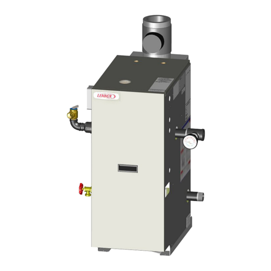
GAS FIRED BOILER
RETAIN THESE INSTRUCTIONS FOR
FUTURE REFERENCE
THESE INSTRUCTIONS MUST BE
AFFIXED ON OR ADJACENT TO THE
!
WARNING
Improper installation, adjustment, alteration,
service, or maintenance could result in death
or serious injury. Refer to this manual for
assistance. For additional information consult
a qualified installer, service agency, or the gas
supplier.
GAS-FIRED HOT WATER BOILERS
These Gas-Fired Water boilers are low pressure,
sectional cast iron boilers Design Certified by CSA
(Canadian Standards Association) for use with
Natural and Propane Gases. They are constructed
and hydrostatically tested for a maximum working
pressure of 100 psi with A.S.M.E. (American
Society of Mechanical Engineers) Boiler and
Pressure Vessel Code Section IV Standards for
Cast Iron Heating Boilers.
C.S.A. Certified
For Natural Gas Or Propane
BOILER.
Tested For 100 psi.
ASME
Working Pressure
PN 240012889, Rev. A [07/31/2020]
Advertisement
Table of Contents

Related Manuals for Lennox GWB84-060E


Summary of Contents for Lennox GWB84-060E
- Page 1 INSTALLATION INSTRUCTIONS PRODUCT LITERATURE Lennox Industries Inc. GWB84-060E, GWB84-095E, Dallas, Texas GWB84-120E, GWB84-150E, GWB84-175E, GWB84-205E, GWB84-235E GAS FIRED BOILER RETAIN THESE INSTRUCTIONS FOR FUTURE REFERENCE THESE INSTRUCTIONS MUST BE AFFIXED ON OR ADJACENT TO THE BOILER. WARNING Improper installation, adjustment, alteration, service, or maintenance could result in death or serious injury.
- Page 2 VERIFY CONTENTS RECEIVED Fully Assembled Boiler Vent Damper Draft Hood Pump (Optional) *Black Iron Fittings *Drain Valve *ASME Safety Relief Valve *Tridicator (see parts list for sizes and use) Includes Essential Documents and Warranty 11x17 Wire Diagrams Document Package *Circulator Harness *Junction Box * Items found in parts box included with your boiler.
-
Page 3: Table Of Contents
TABLE OF CONTENTS 1 - Physical Data ........................4 2 - Safety Symbols And Warnings ....................5 3 - Locating The Boiler ....................... 7 3.1 Installation Requirements ........................7 3.2 Clearance And Service Requirements ....................7 3.3 Boiler Location Considerations ......................8 4 - Connecting Supply And Return Piping ................... -
Page 4: Physical Data
1 - PHYSICAL DATA Model GWB84-060E GWB84-095E GWB84-120E GWB84-150E GWB84-175E GWB84-205E GWB84-235E # Sections 13-³/8" 13-¹/2" 16-1/4" 19" 21-7/8" 27-¹/2" 27-¹/2" A Width with Jacket 340 mm 340 mm 411 mm 483 mm 555 mm 700 mm 700 mm 6-³/4"... -
Page 5: Safety Symbols And Warnings
2 - SAFETY SYMBOLS AND WARNINGS FOR YOUR SAFETY READ BEFORE OPERATING 2.1. Safety Information DANGER Boiler installation shall be completed by qualified agency. WARNING Fire, explosion, asphyxiation and electrical shock hazard. Improper installation could result in death or serious injury. Read this manual and understand all requirements before beginning installation. - Page 6 2 - SAFETY SYMBOLS AND WARNINGS 2.2 For Your Safety 2.2 For Your Safety WARNING Manufacturer recommends a carbon monoxide detector Manufacturer recommends a carbon monoxide detector Combustion chamber insulation in this product located on each floor of your home. Follow your detector's located on each floor of your home.
-
Page 7: Locating The Boiler
3 - LOCATING THE BOILER 3.2 Clearance and Service Requirements WARNING Allow 24 inches (610 mm ) at front and one side for Fire hazard! Do not install boiler on combustible servicing and cleaning. flooring or carpeting. Failure to follow these When installed in utility room, door should be wide instructions could result in death or serious injury. -
Page 8: Boiler Location Considerations
3 - LOCATING THE BOILER 3.3 Boiler Location Considerations • System piping exposed to freezing conditions: Use inhibited propylene glycol solutions certified by fluid • Ambient room temperature always above 32°F (0°C) to manufacturer for use with closed water heating system. prevent the potential of freezing. -
Page 9: Connecting Supply And Return Piping
4 - CONNECTING SUPPLY AND RETURN PIPING A. connect to relief valve outlet and piped down WARNING to safe point of disposal. Check local codes for Burn and scald hazard! Supply and return shall be maximum distance from floor or allowable safe piped on the same side. -
Page 10: Flush And Rinse System
4 - CONNECTING SUPPLY AND RETURN PIPING 4 - CONNECTING SUPPLY AND RETURN PIPING WARNING 4.4 Water Treatment • Poison hazard. Ethylene glycol is toxic. Do not use ethylene glycol. Manufacturer recommends a water analysis be done on water used to fill the system. Treatment may be required •... -
Page 11: Supply And Return Requirements
4 - CONNECTING SUPPLY AND RETURN PIPING 4 - CONNECTING SUPPLY AND RETURN PIPING 4.5 Supply and Return Requirements Installation using circulators and zone valves are shown in Figures 4-2 through 4-7. For further piping Boiler used in connection with refrigeration system, information refer to AHRI Installation and Piping install so chilled medium is piped in parallel with boiler Guide. - Page 12 4 - CONNECTING SUPPLY AND RETURN PIPING PIPING LEGEND: BACK FLOW VALVE Circulators in following illustrations are mounted on system supply side, mounting on system return side is also acceptable practice. Figure 4-2 - Circulators Mounted on Supply System, Boiler Used In Configuration with Chiller System.
- Page 13 4 - CONNECTING SUPPLY AND RETURN PIPING PIPING LEGEND: BACK FLOW VALVE Figure 4-3 - Bypass Piping With Automatic Mixing Valve PURGE VALVE BACK FLOW VALVE ASME RELIEF VALVE DRAIN VALVE PN 240012889 Rev. A [07/31/2020]...
- Page 14 4 - CONNECTING SUPPLY AND RETURN PIPING PIPING LEGEND: BACK FLOW VALVE Figure 4-4 - Bypass Piping - Fixed Low Temp Only With Zone Valve ASME RELIEF VALVE * Manually adjust until proper system temperature is reached. PN 240012889 Rev. A [07/31/2020]...
- Page 15 4 - CONNECTING SUPPLY AND RETURN PIPING PIPING LEGEND: BACK FLOW VALVE Figure 4-5 - Bypass Piping (4-Way Valve Option With Circulator On Supply side) FLOW CONTROL VALVE ASME RELIEF VALVE DRAIN VALVE PN 240012889 Rev. A [07/31/2020]...
- Page 16 4 - CONNECTING SUPPLY AND RETURN PIPING PIPING LEGEND: BACK FLOW VALVE Figure 4-6 - Single Zone System With DHW Priority Back Flow Valve ASME RELIEF VALVE Purge Drain Valve Valve PN 240012889 Rev. A [07/31/2020]...
- Page 17 4 - CONNECTING SUPPLY AND RETURN PIPING PIPING LEGEND: BACK FLOW VALVE Figure 4-7 - Multi Zone System With Zone Valves And DHW Priority (With Zone Valve) * Hot Water Supply Tempered Tank Sensor Optional Indirect DHW Tank Cold T & P Relief Water Valve to DHW Pump...
-
Page 18: 5- Ventilation & Combustion Air
5- VENTILATION & COMBUSTION AIR 5.1 Requirements B. Known Air Infiltration Rate. See Table 5-1 for space with boiler only. Use equation for multiple WARNING appliances. Do not use an air infiltration rate Asphyxiation Hazard! Provide enough air openings (ACH) greater than 0.60. to boiler/combustion area to dilute flue gases Volume ≥... -
Page 19: Vent System Modification
6 - VENT SYSTEM MODIFICATION 6.1 Removal Of Existing Boiler From Venting System Typical Masonry Chimney Requirements Figure 6-1 - When an existing boiler is removed from a common venting system, the system is likely too large for proper venting of appliances still connected to it. -
Page 20: Vent Installation
7 - VENT INSTALLATION Boiler series is classified as a Category I. Vent WARNING installation shall be in accordance with "Venting of Boiler and venting installations shall be performed Equipment," of the National Fuel Gas Code, ANSI by a qualified expert and in accordance with the Z223.1/NFPA 54, or "Venting Systems and Air Supply for Appliances,"... -
Page 21: Vent Damper Installation & Instructions
8 - VENT DAMPER INSTALLATION & INSTRUCTIONS 8.1 Vent Damper Fasten sections of vent pipe with sheet metal screws to make piping rigid. Support horizontal potions of vent Connecting The Vent Damper And Vent Connector system to prevent sagging. Use stovepipe wires every 5’ to Refer to page 4 for size and location of vent (flue opening). - Page 22 8 - VENT DAMPER INSTALLATION & INSTRUCTIONS Figure 8-2 - Vent Damper Placement Figure 8-3 - Vent Damper Position Indicator PN 240012889 Rev. A [07/31/2020]...
-
Page 23: Connecting Gas Service
9 - CONNECTING GAS SERVICE DANGER Table 9-1 Natural Gas Propane Min. Supply Pressure 5" w.c. 11" w.c. Fire Hazard. Do not use matches, candles, open flames, or other methods providing ignition source. Max. Supply Pressure 13.5" w.c. 13.5" w.c. Failure to comply will result in death or serious 10"... -
Page 24: Electrical
10 - ELECTRICAL WARNING Electrical shock hazard. Turn OFF electrical power supply at service panel before making electrical connections. Failure to do so could result in death or serious injury. WARNING Fire, electrical shock hazard. Verify all electrical connections are secure. Failure to do so could result in death or serious injury. -
Page 25: Wiring Diagrams
11 - WIRING DIAGRAMS WARNING Modification, substitution or elimination of factory equipped, supplied or specified components may result in personal injury or loss of life. Figure 11-1 - 3200 Plus Fuel Smart Hydrostat Control PN 240012889 Rev. A [07/31/2020]... - Page 26 11 - WIRING DIAGRAM Figure 11-2 - 3200 Plus Fuel Smart Hydrostat Control - Ladder PN 240012889 Rev. A [07/31/2020]...
-
Page 27: Lighting Instructions
12 - LIGHTING INSTRUCTIONS 12.2 Operating Instructions For Intermittent WARNING Pilot System If you do not follow these instructions STOP! Read and follow all safety information. exactly, a fire or explosion may result causing property damage, personal injury or loss of Set the thermostat to lowest setting. -
Page 28: Normal Sequence Of Operation
13 - NORMAL SEQUENCE OF OPERATION WARNING A. Power remains off until boiler water temperature drops below high limit setting. Burn Hazard. View port on burner door may be hot. B. Circulator continues to operate under this condition Wear personal protection when servicing this boiler. until thermostat is satisfied. -
Page 29: General Maintenance And Care Instructions
14 - GENERAL MAINTENANCE AND CARE INSTRUCTIONS 14.2 Clean Flue Gas Passageways WARNING Follow this procedure to clean flue gas passageways: Label all wires prior to disconnection when servicing controls. Wiring errors could cause improper and Remove burner tray from heat exchanger by disconnecting gas valve, remove two (2) nuts and pull dangerous operation. -
Page 30: General Maintenance
14 - GENERAL MAINTENANCE AND CARE INSTRUCTIONS 14.3 General Maintenance Figure 14-1 - Burner Tray BURNERS • Visually inspect main burner and pilot flames at start of heating season and again in mid-season. ◊ Main burner flame should have well defined inner GAS VALVE blue mantel with lighter blue outer mantel. -
Page 31: Adjusting Gas Input
14 - GENERAL MAINTENANCE AND CARE INSTRUCTIONS 14.4 Adjusting Gas Input Adjust gas input to boiler by removing protective cap on pressure regulator and turning screw clockwise increase input and counterclockwise to decrease input. See Figure 12-1 page 27. Manifold pressures are taken at outlet side of gas valve. -
Page 32: Ratings And Capacities
15 - RATINGS AND CAPACITIES EXPLANATORY NOTES All boilers are design certified for installation on noncombustible floor. FOR INSTALLATION ON NON-COMBUSTIBLE FLOORS ONLY - For installation on combustible flooring special base must be used. (See Combustible Floor Addendum). Do NOT install boiler on carpeting. Recommended chimney height 20 feet. -
Page 33: Appendix A - Control Function
APPENDIX A - CONTROL FUNCTION ECONOMY TARGET When the Economy feature is WARNING active, the Fuel Smart HydroStat continually sets Burn and scald hazard. Do not add water until boiler target temperatures below the high limit setting has fully cooled. Failure to follow these instructions to maximize fuel efficiency. -
Page 34: A-1. Intermittent Pilot
APPENDIX A - CONTROL FUNCTION A-1. Intermittent Pilot If this LED is blinking and the burner is not firing: Make sure the plug connection (or jumper, on Ignition System Checks boilers where vent damper plug is not used) is secure. STEP 1: Check ignition cable. - Page 35 APPENDIX A - CONTROL FUNCTION Recheck ignition sequence as follows: STEP 3: Check spark ignition circuit. a. Reconnect main valve wire. Disconnect ignition cable at SPARK terminal on module. b. Adjust thermostat above room temperature. WARNING c. Verify ignition sequence at burner. d.
-
Page 36: Appendix B-1 - Vent Damper Installation
APPENDIX B-1 - VENT DAMPER INSTALLATION WARNING Figure B-1a - Horizontal Installations Flow Asphyxiation, burn hazard. Improper operation of vent damper may result in serious injury or death due to fire or to asphyxiation from poisonous gases Vent Damper o Chimney To Boiler such as carbon monoxide which is odorless and Install vent damper with actuator to sides of... -
Page 37: Appendix B-2 - Vent Damper Harness
APPENDIX B-2 - VENT DAMPER HARNESS B.1 Vent Damper Harness - Molex Plugs C. Remove damper harness from control. Jump Molex connector on control board between two center WARNING holes using ~ 18 ga. thermostat wire. Follow all instructions regarding safety operational If boiler ignites, replaces damper harness controls in this manual. -
Page 38: Appendix B-3 - Vent Damper Troubleshooting
APPENDIX B-3 - VENT DAMPER TROUBLESHOOTING B.2 Vent Damper Troubleshooting Guide Normal Sequence of Operation WARNING 24 VAC Power ON Damper Position Follow all instructions regarding safety operational Power controls in this manual. Failure to follow these 4 & 1 All times Open or Closed instructions could result in death or serious injury. - Page 39 APPENDIX B-3 VENT DAMPER TROUBLESHOOTING For troubleshooting only. Verify damper is in NOTICE Note open position. Use service switch to keep Service Switch: The service switch does not damper in open position. Place jumper between complete the vent damper end switch circuit; it is 2 &...
- Page 40 • This boiler is not used for any space heating • This boiler is part of a modular or multiple boiler system having a total input of 300,000 BTU/hr or greater. • This boiler is equipped with a tankless coil. PRODUCT LITERATURE Lennox Industries Inc. Dallas, Texas...
Need help?
Do you have a question about the GWB84-060E and is the answer not in the manual?
Questions and answers