
Subscribe to Our Youtube Channel
Related Manuals for Plura ELC


Summary of Contents for Plura ELC
- Page 1 Functional Description and Specifications Version: 2.1 September 25, 2019 Ethernet to LTC Convertor...
-
Page 3: Table Of Contents
Functional Description and Specifications ELC Page 3 CONTENTS REVISION HISTORY COPYRIGHT CERTIFICATIONS & COMPLIANCES WARRANTY UNPACKING/SHIPPING/REPACKAGING INFORMATION DESCRIPTION INTRODUCTION CONNECTIONS AND SPECIFICATIONS POWER SUPPLY STATUS INDICATION BY LED MOUNTING FIRMWARE UPDATE SOFTWARE TOOLS FOR ELC THE UD/SC CONFIGURATION PROGRAM THE INTEGRATED ETHERNET SERVER CONFIGURATION 3.3.1... - Page 4 September 25, 2019 Changed address of Plura Europe GmbH. Due to constant product development the features of ELC are subject to change. The current functional description always refers to the current firmware and the current configuration tool. You can download the latest version of the standard firmware from https://www.plurainc.com.
-
Page 5: Copyright
Page 5 Copyright Copyright © Plura Europe GmbH 2012-2019. All rights reserved. No part of this publication may be reproduced, translated into another language, stored in a retrieval system, or transmitted, in any form or by any means, electronic, mechanical, photocopying, recording, or otherwise without the prior written consent of Plura Europe GmbH. -
Page 6: Warranty
This warranty is given by Plura with respect to this product in lieu of any other warranties, express or implied. Plura and its vendors disclaim any implied warranties of merchantability or fitness for a particular purpose. -
Page 7: Unpacking/Shipping/Repackaging Information
Ensure that all packaging material is removed from the product and its associated components before installing the unit. Products returned to Plura for servicing or repair should have a tag attached showing: • Name and complete address of the owner and the name of the person that can be contacted. -
Page 8: Description
Description 1.1 Introduction ELC serves as an LTC generator with two output stages. The data content within the LTC time code is either fed from an NTP server or an MTDoE master device. Both LTC output signals are phase locked to UTC time which is available as well in NTP mode as in MTDoE mode. Time addresses as well as user data (binary groups) of the LTC can be independently configured and generated. -
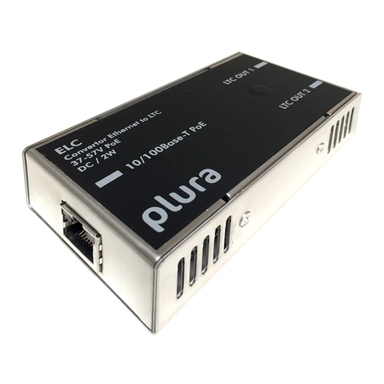
Page 9: Connections And Specifications
Functional Description and Specifications ELC Page 9 1.2 Connections and Specifications 10/100Base-T PoE LTC OUT 2 LTC OUT 1 STAT RJ45 jack 1: Tx+ / V 2 x RJ45 jack 2: Tx– / V 3: Rx+ / V – Green LED STAT... -
Page 10: Power Supply
Page 10 1.3 Power Supply ELC receives power via “Power over Ethernet“ (PoE). Power over Ethernet or PoE technology describes a system to pass electrical power, along with data, on Ethernet cabling. Just connect ELC to a PoE port of a switch. -
Page 11: Status Indication By Led
No LTC output. twice per second NTP server lost “Source = NTP”: Timeout, communication between ELC and NTP server is disrupted. turns off shortly twice per second As long as the LTC output is switch on, LTC will be generated. -
Page 12: Mounting
Functional Description and Specifications ELC Page 12 1.5 Mounting There are two threaded holes (M3) at the bottom of the unit. Maximum screw-in depth: 15 mm/0.59 inches. 100 mm 50 mm Alpermann+Velte Drawing not to scale! PREVENT OVERHEATING To prevent product overheating, position the unit only where sufficient air circulation can be maintained. -
Page 13: Firmware Update
Execute UD SC Config on your computer. The program gives a list of all MTD devices found in the network. ELC should be on this list. Access via Ethernet can be protected by a password (please refer to chapter “System”: View and Change System Parameters). -
Page 14: Software Tools For Elc
Software Tools for ELC 3.1 The UD/SC Configuration Program Via the UD SC Config program, you can locate and setup ELC units in your network. It runs on a computer (32/64-bit Windows operating systems 2000/XP/2003/Vista/2008/7). You can download the latest version of the program from: https://www.plurainc.com. -
Page 15: The Integrated Ethernet Server
Page 15 3.2 The Integrated Ethernet Server Start an Internet Browser and type in the IP address of ELC. If you do not know the IP address, start the UD SC Config program (refer to chapter “The UD/SC Configuration Program”). -
Page 16: Configuration
3.3 Configuration 3.3.1 General You can do a set-up of ELC via the UD SC Config PC program or via the integrated Ethernet server. Set-up via UD SC Config: After program start the ELC module should appear in the list. Select the ELC line and click button , or double click on the line –... -
Page 17: Profile": Store And Load A Complete Set-Up
Functional Description and Specifications ELC Page 17 “Profile“: Store and Load a Complete Set-Up 3.3.2 Configuration options (example shows a screen shot of the Ethernet server): This feature enables to easily change the complete set-up of the unit during normal operation. -
Page 18: System": View And Change System Parameters
Configuration options (example shows a screen shot of the Ethernet server): Unit Name Give the device a significant name. This name appears wherever ELC devices can be found. Enter a text (10 characters) in the Name field. Complete with Enter or Tab key. -
Page 19: Source": Select The Signal Source
3.3.4 Configuration options (example shows a screen shot of the Ethernet server): ELC is able to convert data of an MTDoE system to LTC. These data include six independent programmable timers, real-time, date, and a time of a time code. -
Page 20: Ethernet": Set-Up Of Network Parameters
Functional Description and Specifications ELC Page 20 “Ethernet“: Set-Up of Network Parameters 3.3.5 Configuration options (example shows a screen shot of the UD SC Config PC program): “Source = MTD“ “Source = NTP“ Current Settings This box indicates the current network parameters of the device. - Page 21 Functional Description and Specifications ELC Page 21 MTD - if “Source = MTD“ has been selected Automatic MTD Master IP Address If checked, the device will automatically find the MTDoE central unit responsible for the group number below. In a redundant system (two MTDoE central units), an automatic changeover can take place in case one central unit fails.
-
Page 22: Real-Time": Ntp Real-Time Parameters
Configuration options (example shows a screen shot of the Ethernet server): ELC receives time & date from an NTP server according to the set-up at the “Ethernet” tab. Time and date refers to UTC (Universal Time Coordinated = world time reference without a Daylight-Saving Time [DST]). -
Page 23: Output": Set-Up Of Ltc Outputs
Functional Description and Specifications ELC Page 23 “Output“: Set-Up of LTC Outputs 3.3.7 Configuration options (example shows a screen shot of the Ethernet server): Frame Rate Select the frame rate of both LTC outputs: Auto 30 df / 29.97 Please note: An LTC counting for a 29.97 Hz system (drop-frame mode) has severe difficulties in a real-time application, because an odd number of frames per second will be generated. - Page 24 Functional Description and Specifications ELC Page 24 LTC 1 / LTC 2 Data content and level of both LTC outputs can be set individually. The mode of synchronization is fixed for both outputs, so that each time code word starts at exactly the same time.
- Page 25 Functional Description and Specifications ELC Page 25 Date coded according to the “EBU Technical Information I29- 1995” (so-called BBC format). The date is BCD coded and assigned to the binary groups as follows: Reserved All bits = 0 Units of the day...
- Page 26 The LTC word can be generated with a “forward” or “reverse” code. Independent from this, the time addresses of the LTC can count upwards, downwards, or can stop counting. This especially will become true if ELC generates the time of a stop timer (e.g. timer A of the MTD system).
-
Page 27: Applications
Applications 4.1 MTD Timer System and LTC Displays ELC offers an easy and cost-effective opportunity to display UP or DOWN counters of the Plura MTD system at Non-Plura displays. These displays must be able to read SMPTE/EBU time code (LTC). -
Page 28: Generate Ltc - Utc And Ltc - Local Time
Functional Description and Specifications ELC Page 28 4.2 Generate LTC - UTC and LTC - Local Time ELC offers an easy and cost-effective opportunity to provide one LTC line with UTC reference time and a second LTC line with local time. LTC - UTC... - Page 30 www.plurainc.com U.S.A. · Germany · U.A.E. · S. Korea...
Need help?
Do you have a question about the ELC and is the answer not in the manual?
Questions and answers