Table of Contents
Advertisement
Quick Links
User Manual
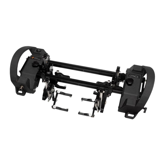
LYNCS™
Weld inspection and corrosion mapping scanner
© Eddyfi UK Ltd
Clos Llyn Cwm, Swansea Enterprise Park,
Swansea,
SA6 8QY, Wales, UK.
Eddyfi UK Ltd (Eddyfi), formerly Silverwing UK Ltd is a wholly owned subsidiary of Eddyfi NDT Inc.
TM
LYNCS
User's Manual
Manual Version 1.0
The text, figures and programs have been worked out with the utmost care. However, we cannot accept either legal responsibility
or any liability for any incorrect statements which may remain, and their consequences. The following documentation is protected
by copyright. All rights reserved.
Eddyfi reserves the right to continue developing the system and software without documenting each individual case. Eddyfi holds
no responsibility for any damage or destruction caused when following instructions within this manual.
1
Advertisement
Table of Contents

Subscribe to Our Youtube Channel
Related Manuals for Eddyfi Technologies LYNCS-WI


Summary of Contents for Eddyfi Technologies LYNCS-WI
- Page 1 User Manual LYNCS™ Weld inspection and corrosion mapping scanner © Eddyfi UK Ltd Clos Llyn Cwm, Swansea Enterprise Park, Swansea, SA6 8QY, Wales, UK. Eddyfi UK Ltd (Eddyfi), formerly Silverwing UK Ltd is a wholly owned subsidiary of Eddyfi NDT Inc. LYNCS User’s Manual Manual Version 1.0...
-
Page 2: Table Of Contents
Safety Markings and Symbols ......................... 3 Copyrights ............................... 3 LYNCS ................................4 LYNCS Scanner Frame Overview ........................5 LYNCS-WI Overview ............................9 LYNCS-WI Operation ............................. 14 LYNCS-CM Overview ............................. 15 LYNCS-CM Operation ............................ 17 LYNCS System components ........................... 18 LYNCS Maintenance ........................... 19 Maintenance .............................. -
Page 3: General Precautions And Conventions
General Precautions and Conventions... -
Page 4: General
General The following precautions are to be observed at all times when using the LYNCS scanner. Please review them before utilising the system. • Keep this document in a safe place for future reference. • Observe all warnings, notes and instructions as marked on the packaging, the scanner and the user manual. -
Page 5: Lyncs Tm
LYNCS... -
Page 6: Lyncs Tm Scanner Frame Overview
LYNCS Scanner Frame Overview Top View Side View Rear View... - Page 7 1. On Board Controls Use this button for Pause / Resume or Increment / Encoder Reset functionality (depending on hardware setup). See LYNCS WI and LYNCS CM overviews for hardware setups. 2. Scanner Frame / End Caps Scanner frame: Used to mount the tractor units, tool posts and corrosion mapping mount. End Caps: Remove end caps via two captive thumbscrews to insert / remove the tractor units, tool posts or corrosion mapping mount.
- Page 8 Prior to use, ensure the umbilical strain relief is correctly applied as described above. Failure to do so could result in damage to the assembly. 9. Encoder Records the distance travelled. 10. Handles / Tether points Handles: Used to deploy, move and remove the scanner. Ensure the handles are used at all times when handling or operating the scanner.
- Page 9 12. Magnetic Wheels The four wheels provide permanent magnetic attraction to the inspection surface. Common Specifications: Minimum surface temperature -30°C (-22°F) Maximum surface temperature +80°C (176°F) Minimum ambient temperature -20°C (-4°F) Maximum ambient temperature +50°C (122°F) Minimum storage temperature -10°C (14°F) Maximum storage temperature +40°C (104°F) Circumferential scanning...
-
Page 10: Lyncs-Wi Overview
LYNCS-WI Overview Top View Tool Post Assembly Side View... - Page 11 1. Outer Tool Posts Wedge tool posts that mount to the outside of the scanner frame. Outer tool posts have a single rail mounting point. 2. On Board Controls Use this button for Pause / Resume functionality. To use Pause / Resume functionality, ensure encoder cable is plugged directly into the instrument and scanner.
- Page 12 4. Inner Tool Posts Wedge tool posts that mount to the inside of the scanner frame. Inner tool posts have a rail mount on either side of the tool post. 5. Tool Post Tilt Adjustment Used to tilt outer tool posts forwards for lower diameter pipework. To tilt the tool post forwards, loosen thumbscrew and move to desired position: Tighten thumbscrew to lock tool post in place.
- Page 13 8. Tool Post Arms / Wedge Mounting Points Used to mount varying wedge widths. To adjust the width of the tool post arms, loosen thumbscrew at rear of tool post and move arm to desired position, tighten thumbscrew to lock tool post arm in place: Threaded holes are used to receive 5mm and 8mm diameter wedge mounts (1 &...
- Page 14 LYNCS WELD SPECIFICATIONS Dimensions Short bar 487 × 198 × 109 mm (19.2 × 7.8 × 4.3 in) (w × d × h) Medium bar 575 ×198 × 109 mm (22.6 × 7.8 × 4.3 in) Short 412 mm (16.2 in) Bar width options Medium 500 mm (19.7 in)
-
Page 15: Lyncs-Wi Operation
10. Tether scanner from both handles. 11. Setup data acquisition unit – for M2M instruments select LYNCS-WI in scanner list NOTE: Typical encoder resolution: 25.85 pts/mm. 12. Perform encoder calibration and complete remaining setup configuration. -
Page 16: Lyncs-Cm Overview
LYNCS-CM Overview Top View Isometric View 1. On board controls Use this button for Increment / Encoder Reset functionality or Pause / Resume functionality. To use Increment / Encoder Reset functionality, plug adapter cable supplied into the instrument side of the encoder cable. - Page 17 4. Corrosion mapping mount Houses the supplied waterbox and clicks into each rail hole via the on-board lever lock along the length of the rail. Lever lock on mount should sit on the same side as the rail with the drilled holes. 5.
-
Page 18: Lyncs-Cm Operation
LYNCS-CM Operation 1. Remove one tractor assembly. 2. Slide on any cable management guides required. 3. Arrange tractor units and affix waterbox mount onto rail depending on required application 4. Insert waterbox and secure into waterbox mount. The waterbox height will need to be adjusted when on test item. -
Page 19: Lyncs System Components
Imperial 26.6” (2) Removable central handle Waterbox Mount Umbilical (5m or 15m / 16.4ft or 49.2ft) Waterbox foam seals (25) LYNCS-WI Nanuk transport PELI-CASE Umbilical (5m or 15m / 16.4ft or 49.2ft) Hose guides (4) LYNCS Frame - 412mm / 16.2”... -
Page 20: Lyncs Tm Maintenance
LYNCS Maintenance... -
Page 21: Maintenance
Reset Contained within accessories tool case in transit Pre-Amp mounting Universal straps not located case lid. *Only supplied with LYNCS-FULL & LYNCS-WI Technical Support For technical support, please contact the following email addresses; Scanner support - support-sw@eddyfi.com Capture support -... - Page 22 Encoder swap out 1. Remove four socket cap bolts. 2. Carefully lift off handle cover, making sure not to place excess strain on wiring. 4. Remove Fischer socket nut and disconnect JST 3. Remove three socket cap bolts and encoder connector (white part in image) to remove housing.
Need help?
Do you have a question about the LYNCS-WI and is the answer not in the manual?
Questions and answers