Table of Contents
Advertisement
Quick Links
Advertisement
Table of Contents
Troubleshooting

Subscribe to Our Youtube Channel
Related Manuals for Eddyfi Technologies LYFT


Summary of Contents for Eddyfi Technologies LYFT
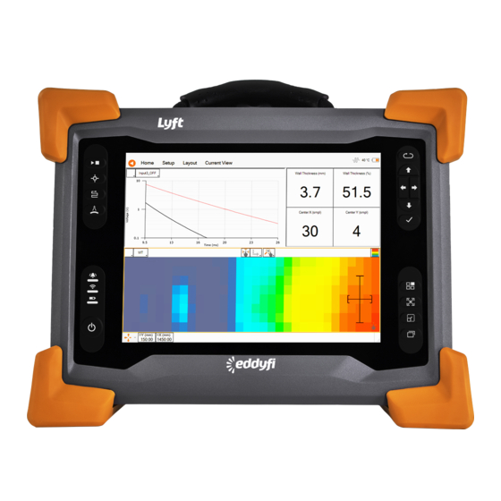
- Page 1 User’s Manual EDDYFI LYFT Corrosion Assessment Redefined...
- Page 2 3425 Rue Pierre-Ardouin Québec (QC) G1P 0B3 CANADA Eddyfi, Lyft, SmartPULSE, and their associated logos are trademarks or registered trademarks of Eddyfi NDT, Inc. Eddyfi reserves the right to change product offerings and specifications without notice. 2020-08-04 ii | eddyfi.com...
-
Page 3: Table Of Contents
Calibration and Warranty Seals ....................xv Limited Warranty ........................xvi Copyrights ..........................xvi Lyft System Overview ....................... 1 Introducing the Lyft System ..................... 2 Positioning Lyft ........................9 Starting Lyft ........................... 11 Shutting Down Lyft ......................... 11 Connecting Probes ........................11 Batteries .......................... - Page 4 Generating a Report ......................44 Managing Data ........................45 Disabling and Enabling the Multi-Touch Display ............... 48 Remote Control Reference ..................... 48 Lyft PRO software ........................53 Lyft Pro ..........................54 Preferences ........................... 58 Managing Preferences ......................59 Keypad and Keyboard Functions ....................63 Keyboard Shortcut Keys ......................
- Page 5 General Precautions and conventions HDMI Connector ........................81 USB Connectors ........................82 Audio Jack ..........................82 Using the Optional Harness ....................83 Adjusting the Harness ......................84 Setting Up the Extension Pole ....................93 Setting Up the Extension Pole ....................94 Using the array probe straps ....................
- Page 6 Figure 1-6 Single element extension pole ................... 7 Figure 1-7 PECA-6CH-MED probe ....................7 Figure 1-8 PECA-HR-SM probe ....................8 Figure 1–9 Lyft in the horizontal position .................. 10 Figure 1–10 Lyft in the tilted position ..................10 Figure 1–11 Shutting down Lyft ....................11 Figure 1–12 Optional battery charger ..................
- Page 7 General Precautions and conventions Figure 2–15 Current A-Scan View Ribbon .................. 28 Figure 2-16 Current Tau-scan View Ribbon ................28 Figure 2–17 Current C-Scan View Ribbon .................. 29 Figure 2–18 Current Information View Ribbon ................29 Figure 2–19 Analysis Ribbon ....................30 Figure 2–20 Edge smoothing dialog box ...................
- Page 8 Figure 3-22 Help section ......................47 Figure 3-23 Setup Tab ......................48 Figure 4–1 External Path Selection dialog box ................54 Figure 4–2 Scan Area section ....................55 Figure 4–3 Calibration Propagation dialog box ................55 Figure 4–4 Selecting the C-scan ....................56 Figure 4–5 CWT% C-scan .......................
- Page 9 General Precautions and conventions Figure B–7 Unfastening the straps ................... 87 Figure B–8 Sliding strap loop through bumper hook ..............88 Figure B–9 Securing anchor strap .................... 88 Figure B–10 Alternative method of securing anchor strap to bumper .......... 89 Figure B–11 Anchor strap on harness belt .................
- Page 10 Tables Table 1-1 Lyft single-element probe status LEDs ........Error! Bookmark not defined. Table 1-2 Lyft array probe status LEDs ..................9 Table 2-1 Multi-touch behavior in the C-scan view ..............25 Table 3-1 Analysis mode remote control reference ........ Error! Bookmark not defined.
-
Page 11: General Precautions And Conventions
General Precautions and conventions General Precautions and conventions | xi... -
Page 12: Safety Precautions
Because Lyft is a portable system, it is designed to be used under tough conditions. It is, however, not indestructible. To avoid damaging Lyft, use its rear stand when operating Lyft in a tilted position. Do not use Lyft in the upright position, as it may topple over or fall off the work surface. Conventions... - Page 13 General Precautions and conventions Bold Used to indicate menu items, named user interfaces, and place emphasis on specific words or phrases. Items in bold type are capitalized to reflect the actual interface. SMALL CAPITALS Used to indicate instrument interface indications Marking and Symbols The following symbols appear on the instrument and pertain to safety regulations that should be carefully observed:...
-
Page 14: Acronyms
Safety Indications in This Document The safety indications in this document are intended to ensure your safety and the integrity of the system. Warning The warning indication calls your attention to a procedure or a practice (or the like) that, if performed incorrectly, can result in injury. Do not ignore warning indications —... -
Page 15: Calibration And Warranty Seals
This device complies with Australia and New Zealand AS/NZS 4252.2 (IEC 61000-6-4) and AS/NZS 61000-6-2 (IEC 61000-6-2). Calibration and Warranty Seals The calibration seal is at the back of the instrument. Lyft is also equipped with a warranty seal. Important Broken seals void the calibration certification and product warranty. -
Page 16: Limited Warranty
Limited Warranty Eddyfi NDT, Inc. warrants the hardware to be free of any defects in materials or workmanship for a period of twelve (12) months from the date of delivery, under normal use and service. These warranties are limited to the original purchase of the product and are not transferable. Eddyfi NDT, Inc. -
Page 17: Lyft System Overview
Lyft System Overview Chapter 1 Lyft System Overview... -
Page 18: Introducing The Lyft System
Introducing the Lyft System Thank you for purchasing Eddyfi’s Lyft®. This chapter is intended to give you an overview of the system and its components before operation. What’s in the Box Lyft comes with the following standard accessories: • Two, high-capacity batteries •... - Page 19 The four corner bumpers provide shock If the instrument is off, a long press will absorption and support Lyft at an angle when activate RDAU mode, which allows the user to it is set on a flat surface. The bumpers are also operate the instrument remotely from a hooked for harnessing.
-
Page 20: Figure 1-2 Rear View
Rear Figure 1-2 Rear view Instrument stand This stand retracts outward to hold Lyft at an angle, preventing the instrument from falling over horizontally. Right Figure 1-3 Right side view I/O connector 2. PEC connector Used to communicate with the probe’s... -
Page 21: Figure 1-4 Left Side View
USB 2.0 connectors Audio connector Use these connectors to hook up USB devices Use this connector to hook up a headset to Lyft such as a mouse or external disk drive. to Lyft. Power connector HDMI® connector Use the supplied power cord to operate Lyft Use this connector to hook up an and recharge the batteries. -
Page 22: Figure 1-5 Single Element Probes
Single-element Probe Overview Lyft single-element probes come in three sizes, small, medium, and large. They feature the same components. Figure 1-5 Single element probes Second-generation probes First-generation probes 3. Built-in encoder Status LEDs First-generation probes are equipped with a The green LED on the left and the red high-precision, 20.53 counts/mm encoder. -
Page 23: Figure 1-6 Single Element Extension Pole
Lyft System Overview Single-Element Probes Accessories For details about these accessories, refer to the PEC probe catalog. Single-Element Extension Pole Overview For details about how to install a single-element or splash zone probe on the extension pole, see Setting Up the Extension Pole page 94. -
Page 24: Figure 1-8 Peca-Hr-Sm Probe
The probes are equipped with the same buttons as single-element probes. The red, green, and blue LEDs indicate the operational status of the probes. Figure 1-8 PECA-HR-SM probe The encoder on the PECA-HR-SM is the same clip-on encoder as the single-element probes. The PECA-6CH-MED probe has a longer travel. -
Page 25: Positioning Lyft
Lyft has two safe operating positions: horizontal and tilted. To use Lyft in a tilted position, simply pull out the stand located at the rear of the instrument until Lyft is at the desired angle. If you are using Lyft with the optional harness, see Adjusting the Harness on page 84... -
Page 26: Figure 1-9 Lyft In The Horizontal Position
Figure 1–9 Lyft in the horizontal position Figure 1–10 Lyft in the tilted position 10 | eddyfi.com... -
Page 27: Starting Lyft
It is possible to use Lyft while it rests on its lower bumpers, but this is not a safe operational position as the instrument may fall over. If you want to use Lyft at an angle, use the stand located at the rear of the instrument. -
Page 28: Batteries
Slide the battery out of its cradle. Hot Swapping Batteries You can remove one of Lyft’s batteries when the instrument is turned on as Lyft can operate with a single battery. Should the power in the remaining battery be insufficient to keep Lyft operating, the instrument shuts down without damaging electronic components, but all your work in progress in the Lyft software (acquisition, etc.) is lost. -
Page 29: Figure 1-12 Optional Battery Charger
Lyft’s transport case is outfitted with two slots intended for the batteries. We recommend that you take advantage of them. - Page 30 14 | eddyfi.com...
-
Page 31: Software Overview
Software overview Chapter 2 Software overview | 15... -
Page 32: Introducing The Lyft Software
Introducing the Lyft Software The software running on Lyft® is a powerful and easy-to-use acquisition and analysis software. It is specifically designed for pulsed eddy current inspections and relies on intuitive wizards to configure setups. The software benefits from a graphical user interface (GUI) designed to simplify the inspection process and enhance your experience. -
Page 33: Figure 2-2 Backstage View: Scan Area
Software overview Scan Area Section This section of the backstage contains information about the loaded scan zone and all the scan zones of the component. This is where you (upper portion of the view): • Create setups • Start inspections •... -
Page 34: Figure 2-3 Backstage View: Report Summary
Report Summary Section This section of the backstage serves to configure the summary included with your reports. This is where you can: Add information about the component type, serial number, operator, service company, etc. • • Create new information fields to be included in reports •... -
Page 35: Figure 2-4 Backstage View: Documentation
Figure 2–5 Backstage view: Help To send Lyft data for support from Eddyfi team, you can use the “support package button”. This allows you to send us data via Wi-Fi without external operation. -
Page 36: Figure 2-6 Support Package Window
Figure 2-6 Support package window Front Stage Overview The front stage displays all the information about your current inspection. This is where you will find all the tools to acquire, save, and analyze inspection data. Figure 2–7 Front-stage view 20 | eddyfi.com... - Page 37 Software overview Backstage icon Tap to access the backstage view. 2. Ribbon-style menus These five menus allow you to perform several inspection operations. Read on for details. 3. Status icons These icons convey unit status information graphically. Keep reading for details. 4.
-
Page 38: Figure 2-8 A-Scan View
The delays are linked with the dot line and indicate the delay in signal due to weather jacket. A difference between both numbers can indicate a wrong setup or a possible jacket overlap. 2. The help button, only in Lyft Pro, is a link to the Help page explaining the τ-scan on the Eddyfi Website. -
Page 39: Figure 2-10 C-Scan View
WL%: wall loss in % according to the nominal wall thickness • • CWT% (only available in Lyft Pro): Compensated remaining wall thickness in % according to the nominal wall thickness 2. Resize cursor button (toggle behavior) 3. Cursor axis selection for Resize action 4. - Page 40 When using an array probe: 1. During acquisition: next position to be When using a single-element probe: acquired on channel 1’s X axis. 1. During acquisition next position to be During analysis: cursor position of acquired on the X axis. During analysis: cursor selected point on the X axis, regardless position on the X axis of the channel used to capture the...
-
Page 41: Figure 2-12 Home Ribbon
Software overview Multi-Touch Interface The Lyft multi-touch interface is designed for ease-of-use. According to your location in the software, the multi-touch behavior changes. The backstage view uses, dialog boxes, and setup wizards, the multi-touch behavior is standard: a short tap on an element of the GUI enables the associated function, exactly as it would at the click of a mouse. - Page 42 1. Acquire 6. Add / Edit Sub-Comp. Tap this button to start and stop your Tap this button to add a new or edit an data acquisition. existing subcomponent region when you must calibrate for different wall thicknesses. 2. Get Point (Grid mode) Tap this button to make one-point 7.
-
Page 43: Figure 2-13 Setup Ribbon
Tap this button to select a scanning pattern 3. WT Calibration and select a grid resolution. Tap this button to calibrate Lyft on a 10. Indication nominal wall or other known thickness . Tap this button to select and configure the 3. -
Page 44: Figure 2-15 Current A-Scan View Ribbon
Tap this button to display or hide the 7. Doc. Tab Notification center tab at the bottom of the Tap to display or hide the Documentation tab front stage. at the bottom of the front stage. Current A-Scan View Ribbon Figure 2–15 Current A-Scan View Ribbon Channel selection 6. -
Page 45: Figure 2-17 Current C-Scan View Ribbon
C-scans. Tap this button to zoom in on to the 10. Move Cursor acquired data content in the C-scan. Tap this button to select the Lyft multi-touch display operational mode (moving the cursor, 4. Palette resizing). Tap this button to open the Palette Selector dialog box. -
Page 46: Figure 2-19 Analysis Ribbon
Analysis Ribbon Figure 2–19 Analysis Ribbon Previous saved in the component folder as if it were Tap this button to select the previous created when entering the defect. The defect indication recorded in the current screenshot appears in the excel report. C-scan 4. -
Page 47: Workflow Overview
Workflow overview Chapter 3 Workflow overview | 31... -
Page 48: Typical Inspection Workflow
TYPICAL Inspection Workflow Figure 3–1 Typical inspection workflow 32 | eddyfi.com... -
Page 49: Creating / Selecting A Project
Workflow overview Creating / Selecting a Project In the General section of the backstage view, tap. The Open dialog box opens. Figure 3–2 Open dialog box 2. Tap an existing project in the project list or tap the Create New button to create a new inspection project. -
Page 50: Adding / Editing A Scan Zone
Figure 3–3 Create Component dialog box 2. Specify all the necessary information, and then tap Finish . Opening an Existing Component In the General section of the backstage, tap the Open Component button. The Open dialog box opens. Figure 3–4 Open dialog box Tap an existing component in the list, and then tap OK . -
Page 51: Creating A Setup
In the Scan Area of the backstage, tap Create Setup . The New Setup Wizard dialog box opens. The probe highlighted in blue is the probe currently connected to Lyft, if any. The recommended probe is indicated in the Suggested column. | 35... -
Page 52: Figure 3-6 Probe Selection
Figure 3–6 Probe selection Connect the recommended probe to Lyft, as necessary. Configure the Line Filter Frequency to the frequency of the power outlet. Tap Next . Figure 3–7 Scan definition 5. On the Scan Mode list, select your scan mode. -
Page 53: Figure 3-8 Encoder Configuration
Workflow overview High resolution: a high-resolution grid resolution is proposed, based on the component • geometry and probe footprint. CWT ready: The resolution is set to allow CWT calculation. • Manual: resolution is set manually • Notes: In dynamic mode, it is possible to configure an external encoder or invert the direction of the •... -
Page 54: Applying Smartpulse Tm
Applying SmartPULSE Quick Procedure 1. In the front stage, on the Home or Setup ribbon, tap SmartPULSE . Figure 3–10 SmartPULSE dialog box 2. Place your probe on the nominal area of the component under test. 3. In the SmartPULSE dialog box, tap Launch . 4. -
Page 55: Figure 3-11 Pec Autoset Dialog Box
Workflow overview Figure 3–11 PEC Autoset dialog box Place your probe on the nominal area of your component. In the PEC Autoset dialog box, tap Run PEC Autoset . To see the signal from your probe, tap Get A-Scan Sample . While the probe is still on the nominal area of your component, in the front stage, on the Setup ribbon, tap WT Calibration . -
Page 56: Acquiring Data
Acquiring Data in Grid Mode Start a data acquisition any of the following three ways: Tap the Acquire button on the Home ribbon of the front stage view. • On Lyft, press • On the probe, press • Place your probe at the coordinates indicated in the information view of the front stage. - Page 57 Workflow overview On the probe, press • Move your probe along the scan axis. To move to the following index: On Lyft, press • On the probe, press • Stop your data acquisition any of the following three ways: Tap the Stop button on the Home ribbon of the front stage view.
-
Page 58: Recalibrating The Wall Thickness
Recalibrating the Wall Thickness If the initial calibration point does not correspond to the nominal value, the C-scan can be recalibrated on a different acquired point. While the cursor is on the nominal area of your component, in the front stage, on the Setup ribbon,tap WT Calibration. -
Page 59: Adding Indications To A Report
Workflow overview Adding Indications to a report If there are any, discard invalid data points near the defect that you want to add. Move the cursor over the target defect. Figure 3–15 Placing cursor over target defect Resize the cursor’s crosshairs so that it covers the entire defect. Click Add Indication . -
Page 60: Generating A Report
Figure 3-17 Indication added Generating a Report In the General section of the backstage, tap Generate Report . The Report Summary dialog box will appear. Figure 3–18 Generate report Type in any missing information and add comments if desired. Click Finish to generate the report. 44 | eddyfi.com... -
Page 61: Managing Data
All the folders in the Projects folder on the Lyft instrument are copied to the USB mass • storage device. All the files in the UserData folder on the USB mass storage device are copied to the Lyft • instrument. -
Page 62: Figure 3-20 Component Transfer Dialog Box
Figure 3–20 Component Transfer dialog box In the Components on External Drive group, select the components that you want to import to Lyft. In the Local Components group, select the project where you want the component to be transferred. Tap Import . -
Page 63: Figure 3-21 Project Transfer Dialog Box
Workflow overview Figure 3–21 Project Transfer dialog box In the Projects on External Drive group, select the projects that you want to import to Lyft. Tap Import . Deleting All User Data To delete all the user data on Lyft, proceed as follows: Connect a USB keyboard to one of Lyft’s USB ports. -
Page 64: Disabling And Enabling The Multi-Touch Display
Disabling and Enabling the Multi-Touch Display Proceed as follows to disable and then re-enable the multi-touch display. You can perform this procedure with a USB keyboard connected to Lyft or with the keypad. Disabling the Multi-Touch Display On the Lyft keypad, long-press Alternatively, you can long-press K on your keyboard. -
Page 65: Table 3-1 Analysis Mode Remote Control Reference
Workflow overview Analysis Mode Table 3-1 Analysis mode remote control reference Grid Mapping Data Acquisiton Table 3-2 Grid mapping data acquisition remote control reference Keypad Operation Acquires a data point at the current cursor Moves to the next acquisition point as defined in the scan parameters on the scan axis (may not be the same direction as the movement of the probe). -
Page 66: Table 3-3 Dynamic Mode Data Acquisition Remote Control Reference
Dynamic Mode Data Acquisition Table 3-3 Dynamic mode data acquisition remote control reference Keypad Operation Pause (first press) and resume (second press) the acquisition process. Moves to the next acquisition point as defined in the scan parameters on the index axis (may not be the same direction as the movement of the probe). -
Page 67: Table 3-7 Wall Thickness Calibration Remote Control Reference
Workflow overview Wall Thickness Calibration Table 3-7 Wall thickness calibration remote control reference Keypad Operation Starts the wall thickness calibration with a new measurement (default setting). Starts a wall thickness calibration with the currently selected area. Moves to the next point on the scan Moves to the previous point on the scan axis. - Page 68 52 | eddyfi.com...
-
Page 69: Lyft Pro Software
Lyft PRO software Chapter 4 Lyft PRO software | 53... -
Page 70: Lyft Pro
C-scans. Transfer Data from Lyft to a computer The data captured with the Lyft instrument can be transferred to Lyft PRO on the PC in two ways: Using a USB key, as explained in Managing Data on page 45 2. -
Page 71: Figure 4-2 Scan Area Section
Lyft PRO software Propagating Calibrations with Lyft Pro Use the Lyft Pro propagate calibration feature to apply one scan zone calibration to other scan zones, created with Duplicate Scan Zone (see Scan Area Section on page 17) In the Scan Area section of the backstage, select and load a scan zone with the calibration you want to apply to other scan zones of the same component. -
Page 72: Figure 4-4 Selecting The C-Scan
To start the process, click OK . Compensated wall thickness C-scan In Lyft and in Lyft PRO, the C-scan can show several different values (click on the icon on top-left of the C-scan to select the desired output): • WT%: remaining wall thickness in % referenced to the nominal wall thickness WT: remaining wall thickness in absolute units •... - Page 73 Lyft PRO software | 57...
-
Page 74: Preferences
Chapter 5 Preferences 58 | eddyfi.com... -
Page 75: Managing Preferences
Company Logo See Managing Data on page 45 to find out how to import your logo to the Lyft instrument Tap Select Company Logo . Select the logo file, and then tap OK... -
Page 76: Figure 5-3 System Preferences
Adjusting the Date and Time of the Lyft Instrument In the System preference section of the backstage, tap Change . A dialog box appears where you can adjust the date, time, and time zone to match requirements. Connecting a Lyft Instrument to a Wi-Fi Network In the System preference section of the backstage, tap Networks . -
Page 77: Figure 5-5 Display Preferences
Preferences Display Preferences In the Display preferences section of the backstage, you can configure a sleep delay of 1 to 30 minutes. By default, the sleep delay is 15 minutes. If active, once this delay expires, the display turns off and the power LED goes from green to red. Figure 5–5 Display preferences To exit the sleep mode, short press the power button, touch the display, or press any of the other keypad buttons. - Page 78 62 | eddyfi.com...
-
Page 79: Keypad And Keyboard Functions
Keypad and Keyboard Functions Chapter 6 Keypad and Keyboard Functions | 63... -
Page 80: Keyboard Shortcut Keys
Table 6-1 Keyboard shortcut keys Further keyboard shortcuts are available and editable from the Keyboard Shortcuts menu for both Lyft and Lyft PRO. To access it, tap the Keyboard button in the Preferences – System page of the Backstage. Figure 6–1 Keyboard Shortcuts dialog box... -
Page 81: Maintenance And Troubleshooting
Maintenance and Troubleshooting Chapter 7 Maintenance and Troubleshooting | 65... -
Page 82: Maintaining Lyft
Maintaining Lyft Because of its design, Lyft® only requires minimal maintenance. Since Lyft has no moving parts, it also does not require any preventive maintenance on your part. We recommend a regular inspection of the instrument to ensure that it is properly grounded. We also strongly recommend an annual calibration and a factory-performed preventive maintenance by an officially qualified Eddyfi technician. -
Page 83: Figure 7-1 Encoder And Replacement Clamp Ring
Maintenance and Troubleshooting Figure 7–1 Encoder and replacement clamp ring Make sure that the pliers are in the “Expanding” configuration as in the following picture. This means that bringing the pliers handles closer to one another drives away the pins from one another. -
Page 84: Figure 7-2 Pliers In Expanding Configuration
Figure 7–2 Pliers in expanding configuration 3. Insert the pins of the pliers inside the replacement camp ring holes. For an easier installation, make sure the ring sits on the extremities of the pin. This will make the installation easier later 68 | eddyfi.com... -
Page 85: Figure 7-3 Clamp Ring Sitting On Plier
Maintenance and Troubleshooting Figure 7–3 Clamp ring sitting on plier 4. Push the encoder connector on the shaft toward the encoder arm. Expand lightly the clamp and install it on the encoder shaft delicately. Figure 7–4 Clamp ring installation 5. Make sure that the retaining clamp is well seated in its grove. | 69... -
Page 86: Updating And Upgrading Software
7. In the list that appears, tap the desired update file, and then tap Update . Important If you are performing a complete Lyft OS update, perform steps 8 to 10. In the case of a software update, the instrument restarts automatically. -
Page 87: Figure 7-6 Update Dialog Box
System Recovery Method (Factory reset) Important Note on System Recovery Before starting the system recovery, check the Lyft Calibration Date on the Calibration Seal attached to the back of the instrument. If the latest Calibration dates before April 2020, please contact Eddyfi (info@eddyfi.com) before executing the System Recovery procedure. -
Page 88: Figure 7-8 System Recovery Interface
4. Wait until a dialog box confirming the activation of Windows appears on screen. If you do not activate Windows, every time you start Lyft, a message will remind you to do so. You have 30 days to activate Windows before it locks up. -
Page 89: Troubleshooting
This appears in the update list or in the system recovery. Make sure that you only have one USB mass storage device connected to Lyft. Also make sure that the file is in the root folder of the device. Cannot display the options screen... - Page 90 74 | eddyfi.com...
-
Page 91: Specifications
Specifications Chapter 8 Specifications | 75... -
Page 92: General
General Table 8-1 General specifications Specification Value Dimensions (W×H×D) 355×288×127 mm (14.0×11.3×5.0 in) With batteries 6.6 kg (14.5 lb) Weight Without 5.7 kg (12.5 lb) batteries Volume 13 L (791 in 100–240VAC ±10 % Power requirements 50–60 Hz Power supply Direct VAC (100 W) or onboard batteries Maximum input current 1.5A... -
Page 93: Probes
Liftoffs: 0–305 mm (0–12in), 0-203 mm (0-8 in), 0-76 mm (0-3 in) Clip-on encoder Models Remote control keypad Lyft 27-pin Fischer connector Heavy-Duty 5m (16.4 ft) cable Carbon steel structures: –150 °C to 500 °C (–238 °F to 932 °F) Testing temperatures Weather jackets: maximum 70 °C (158 °F) - Page 94 78 | eddyfi.com...
-
Page 95: Connector Reference
Connector reference Appendix A Connector reference | 79... -
Page 96: Pec Connector
Ground Reserved Reserved Ethernet Connector The Ethernet connector is used to connect the Lyft to a network through an Ethernet link. Eddyfi supplies a high-quality, military-grade Ethernet connector and cable. International Ethernet standards are used. Table A-3 Ethernet connector data... -
Page 97: Hdmi Connector
Bi_DD– Bidirectional pair D– Important Lyft must be linked to a workstation with a category 5e, shielded, Ethernet cable or better of a maximum length of 100 m (328 ft). HDMI Connector The HDMI connector is used to output video from Lyft to an external display. International HDMI standards are applied. -
Page 98: Usb Connectors
Hot plug detection pin USB Connectors The USB connectors support USB 2.0. You can use the USB connectors to connect USB-compliant devices to Lyft, including external memory, mouse, and keyboard. International USB 2.0 standards are applied. Table A-7 USB connector data... -
Page 99: Using The Optional Harness
Using the Optional Harness Appendix B Using the Optional Harness | 83... -
Page 100: Adjusting The Harness
Adjusting the Harness Harnessing Lyft® requires several specific adjustments so that you feel comfortable wearing the harness. Adjusting the Harness to your Body Grab the harness shoulder straps and slip it over your shoulders as you would a jacket. Figure B–1 Slipping the harness on... -
Page 101: Figure B-2 Adjusting The Shoulder Straps
You may need to perform this adjustment several times to get the proper fit. Note Your belt’s height determines the lowest position of Lyft. Adjust this height so that the display of the instrument is easy to see for that, the belt could end up higher than your hips. -
Page 102: Figure B-4 Securing The Chest Straps
Figure B–4 Securing the chest straps Secure the belt around your waist, according to the height you have adjusted it. Figure B–5 Securing the belt Make sure that the harness fits snuggly. Make sure that the harness’s shoulder anchor straps are loose. 86 | eddyfi.com... -
Page 103: Figure B-6 Shoulder Anchor Straps
Figure B–7 Unfastening the straps Sit down. Place Lyft horizontally in your lap. Slip the looped portion of the strap removed above in the hook of one of the two upper Lyft bumpers, as illustrated. Note Illustrated here is Reddy. Manipulations on Lyft are the same. -
Page 104: Figure B-8 Sliding Strap Loop Through Bumper Hook
Figure B–8 Sliding strap loop through bumper hook Slip the clip through the strap hoop, and then pull to tighten into place, as illustrated. Figure B–9 Securing anchor strap Repeat the previous two steps for the opposite upper bumper. Note You can also secure the straps to the bumpers in a more elegant and less easy-to-remove fashion, as illustrated here. -
Page 105: Figure B-10 Alternative Method Of Securing Anchor Strap To Bumper
Using the Optional Harness Figure B–10 Alternative method of securing anchor strap to bumper Locate the anchor strap on the harness’s belt. Figure B–11 Anchor strap on harness belt Open the battery compartment door and slip the male buckle of the anchor strap, as illustrated. -
Page 106: Figure B-12 Slipping Male Buckle Through Bumper
Figure B–12 Slipping male buckle through bumper Mate the male buckle to its female counterpart. Figure B–13 Mating battery compartment side anchor strap Close and secure the battery compartment door. 90 | eddyfi.com... -
Page 107: Figure B-14 Closing Battery Compartment Door
Mate the left male buckle of the shoulder anchor strap to its female counterpart. Figure B–15 Mating shoulder anchor strap Repeat for the opposite shoulder anchor strap. Tighten each shoulder anchor straps to achieve the desired view angle for Lyft. | 91... -
Page 108: Figure B-16 Tightening Shoulder Anchor Straps
Figure B-16 Tightening shoulder anchor straps Note Use the belt strap to hook your probe’s cable. Figure B–17 Belt-slinging probe cable 92 | eddyfi.com... -
Page 109: Setting Up The Extension Pole
Setting Up the Extension Pole Appendix C Setting Up the Extension Pole | 93... -
Page 110: Setting Up The Extension Pole
Setting Up the Extension Pole The optional extension pole enables you to use Lyft® in hard-to-reach locations. Proceed as follows to ready the system for operation. Installing the Extension Pole Supports on the PEC Probe Locate the pocket on the side of the side of the extension pole carrying case. -
Page 111: Figure C-3 Sliding Pec Probe On Extension Pole Head
Extend the topmost portion of the pole slightly. Close the latch to secure the extension pole. Connecting the Extension Pole to Lyft Run the PEC probe connector and cable through the three hoops on the pole, as illustrated. Figure C–5 Running PEC probe cable through pole hoops Connect the probe cable connector to the remote control on the pole. -
Page 112: Figure C-6 Connecting Pec Probe Connector To Extension Pole Remote Control
Figure C–6 Connecting PEC probe connector to extension pole remote control Connect the remote-control connector to the Lyft PEC connector. 96 | eddyfi.com... -
Page 113: Using The Array Probe Straps
Using the array probe straps Appendix D Using the array probe straps | 97... -
Page 114: Locking And Unlocking The Prove Curvature
Locking and unlocking the prove curvature The array probe curvature can be adjusted to fit on flat surfaces and pipes down to 6 inches outside diameter. The locking mechanism allows you to fix the curvature on the component and ensure a constant fit. -
Page 115: Figure D-3 Probe On A Pipe With Curvature Locked
Using the array probe straps Fitting and locking the probe in position Lay the unlocked probe on a pipe Lock the 6 probe latches delicately. Validate that the encoder wheel is in contact with the component Figure D–3 Probe on a pipe with curvature locked To ease the inspection of pipes, install the carriage accessories and close the strap loops. -
Page 116: Figure D-4 Carriage Installed On The Straps
Figure D–4 Carriage installed on straps Connect the end of the strap loops to the buckles on the other end of the probe Figure D–5 Strap connected to the probe buckles Adjust the position of the carriages on the strap to limit the contact between the straps and the surface Tighten the straps to ensure full support of the probe. -
Page 117: Figure D-6 Handle Installed On Module 6
Using the array probe straps Figure D–6 Handle installed on element 6 Install the marker/pen of your choice in the Grid-As-U-Go system. Figure D–7 Erasable marker installed Install the Grid-As-U-Go system on the probe handle accessory previously installed. | 101... -
Page 118: Figure D-8 Grid-As-U-Go The Peca Probe
Figure D–8 Grid-As-U-Go the PECA probe Remove the marker/pen cap and adjust the pen position in the system using the clamping screw to ensure proper contact on the component surface. Figure D–9 Installed Grid-As-U-Go 102 | eddyfi.com... - Page 119 License management Appendix E License management | 103...
- Page 120 Activate your Go Subscription At least, at renewal, your Lyft unit needs to be connected to the licensing system over internet. To do so, you need to connect an ethernet cable or connect your Lyft to internet via Wi-Fi. Lyft Pro Request temporary license At activation of Lyft 2.3 or later version, a pop-up window requiring an activation code will...
- Page 121 License management -YourComputerID- -Today- -Two weeks later- | 105...
- Page 122 Activation of license At any time during and after the temporary license period, you can active your license code provided by your Eddyfi Representative. -YourLicenseCode- 106 | eddyfi.com...
- Page 123 License management -YourLicenseCode- -YourLicenseCode- -YourComputerID- -YourCompany- -Today- -YourRenewalDate- Release of license To release a license (to share it with a colleague or to change computer), you need to release it. To release it, you only need to click on the “Release button”. Once a license is released, the software cannot be used until reactivation.
Need help?
Do you have a question about the LYFT and is the answer not in the manual?
Questions and answers