Table of Contents
Advertisement
DESCRIPTION
The Fireye InSight Series 4 scanner belongs to an established family of versatile fully microprocessor based,
integrated flame scanners. The InSight Series 4 scanner holds multiple worldwide safety agency approvals (see
Model Listings for full details).
The InSight Series 4 scanners utilize advanced techniques for discrimination and integrate the flame detection,
amplification, safety determination and flame switch functions into a single detection head. No separate amplifier or
flame switch module is therefore required to interface with the main burner management system.
InSight Series 4 incorporates the superior detection and discrimination elements of the popular InSight II product
with some enhanced features.
The scanner measures the amplitude of the modulations (the flame "flicker") that occur within the targeted flame.
During the scanner set-up procedure, the modulation frequency that yields the best flame ON/OFF discrimination is
selected. The appropriate modulation frequency and sensor gain can be either manually or automatically selected.
InSight Series 4 is a solid state detector scanner utilizing either UV or IR detector, and two different available
connectors which are compatible either with the 59-608, 59-547 and 59-497 (-1WINC models) cable.
Standard features include an independently adjustable Flame Relay, 21 choices of modulation frequency, adjustable
sensor gain, adjustable flame relay ON/OFF thresholds, a 4-20 mA analog signal strength output, Fault Relay, four
selectable programmable files (e.g. for different fuels or firing rates), and Auto Config capability with manual
override. Remote communication capability is available via optional "Fireye Explorer" PC software (CU-109).
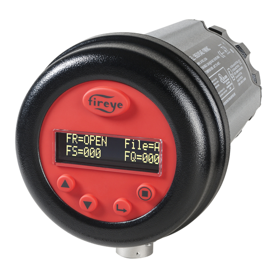
These InSight Series 4 sensors have a two-line by sixteen-character alpha-numeric OLED display with a five-
pushbutton keypad.
The -2 models of the InSight Series 4 (e.g., 95UVS4-2, 95IRS4-2) provide a Form C flame relay output contact
(NO/NC).
© 2020 Carrier
CU-120
June 23, 2020
TYPE 95 Series 4
Integrated Flame
Scanner
SIL3
1
Advertisement
Table of Contents

Related Manuals for Fireye InSight 4 Series


Summary of Contents for Fireye InSight 4 Series
-
Page 1: Description
Scanner SIL3 DESCRIPTION The Fireye InSight Series 4 scanner belongs to an established family of versatile fully microprocessor based, integrated flame scanners. The InSight Series 4 scanner holds multiple worldwide safety agency approvals (see Model Listings for full details). The InSight Series 4 scanners utilize advanced techniques for discrimination and integrate the flame detection, amplification, safety determination and flame switch functions into a single detection head. - Page 2 Before attempting to install, commission, or operate this equipment, all relevant sections of this document must be read and fully understood. If in doubt about any requirements consult Fireye. Installation, commissioning or adjustment of this product MUST be carried out by suitably trained engineers or personnel qualified by training and experience.
-
Page 3: Table Of Contents
Table of Contents DESCRIPTION ............................1 OPERATION ............................4 APPLICATION ............................4 DIMENSIONS ............................6 MODEL LISTING ............................8 SPECIFICATIONS ............................. 9 INSTALLATION NOTES ........................... 10 INSTALLATION PROCEDURE ........................10 MECHANICAL ACCESSORIES ......................... 12 ELECTRICAL ACCESSORIES ........................15 SCANNER WIRING ..........................16 REMOTE FILE SELECTION ........................ -
Page 4: Operation
OPERATION The InSight Series 4 scanner has numerous adjustment options available. It can be tuned either automatically or manually to achieve the optimum level of sensitivity to the target flame balanced with superior discrimination of background radiation. The InSight Series 4 scanner measures the amplitude of the modulations (the flame “flicker”) that occur within the targeted flame. - Page 5 SUGGESTED PROOF TESTS Active Flame OFF test - Shutdown the burner and ensure that the flame off condition is detected and signaled by the flame detector as a flame off condition Active False Flame test - verify that prior to start up (no flame present) there is no indication of a flame on condition (false flame signal) on the flame scanner (this is typically integrated within the Burner Management System as a pre-start permissive to prevent start up if a false flame condition is detected.
-
Page 6: Dimensions
InSight 4 SCANNER FEATURES 95UVS4- 95IRS4- 95UVS4E- 95IRS4E- 95UVS4-1 95IRS4-1 95UVS4-1CEX 95IRS4-1CEX Features 1WINC 1WINC 1WINC 1WINC 95UVS4-2 95IRS4-2 95UVS4-2CEX 95IRS4-2CEX UV or IR Sensor Flame Relay Fault Relay 4-20 mA Output Modulation Frequency Selectors Memory Files Communications Auto Config 2 X 16 Alpha Display Housing Material Aluminum... - Page 7 FIGURE 2. TYPE 95UVS4-1CEX, 95UVS4-2CEX, 95IRS4-1CEX, 95IRS4-2CEX SCANNERS, OPTIONAL FLAME-PROOF HAZARDOUS AREA HOUSING Housing Flange Kit ordered separately, includes NPT or BSP flange, gasket, mounting screws, • PN 129-168-1 (NPT) or PN 129-168-2 (BSP). Suitably rated blanking elements must be used on all unused openings. •...
-
Page 8: Model Listing
MODEL LISTING AGENCY APPROVALS PART CONNECTOR HOUSING SENSOR DIN- DIN- IN-METRO NUMBER TYPE RATING C/US DVGW CERTCO 95UVS4-1 InSight II 95IRS4-1 InSight II 95UVS4-2 InSight II 95IRS4-2 InSight II See note 1 95UVS4- InSight I 1WINC 95IRS4- InSight I 1WINC 95UVS4E- InSight I 1WINC... -
Page 9: Specifications
ELECTRICAL: Input Power: 24 Vdc, +10%, -15% supply current: 0.25A, 6VA, Hold Time must be 20 msec Min. Fireye power supply 60-2685 is recommended Electrical Connection: 12-pin screw type quick-disconnect Relay Output: FLAME RELAY, -1: SPST (N.O.) / -2:SPDT (Form-C) FAULT RELAY, SPST (N.C.) -
Page 10: Installation Notes
Temperature: 257°F (125°C), maximum O.D. 0.43" (10.9 mm) Vibration specs: Frequency range: 10 Hz – 150 Hz. Acceleration / Amplitude: 58 to 150 Hz: 1.0 g / 10 to 58 Hz: 0.075g Sweep rate: 1 octave per minute Number of sweep cycles: 10 Number of axes: 3, mutually perpendicular Note: Wiring is SELV for Input (24V DC) only, and is non-SELV for the other connections. - Page 11 Consideration must be given to burner secondary air rotation, some burners have clockwise (CW) air rotation and others have counterclockwise (CCW) air rotation. If combustion air enters the furnace with a rotational movement of sufficient velocity to deflect the ignitor flame in the direction of rotation, position the scanner 10 to 30 degrees downstream of the ignitor as shown in Figure 4 and close to the periphery of the burner throat (See Figure 3).
-
Page 12: Mechanical Accessories
The scanner lens must be kept free of contaminants (oil, ash, soot, dirt) and the scanner housing temperature must not exceed its maximum rating of 150°F (65°C). Excessive temperatures will shorten scanner life. Both requirements will be satisfied by a continuous injection of purge air at either the 3/8”... - Page 13 FIGURE 6. PART NUMBER A. SWIVEL MOUNT 60-1664-3 (NPT) 60-1664-4 (BSP) B. 1" WYE 35-200 (NPT) C. 1” CLOSE NIPPLE 35-201 (NPT) D. SEALING COUPLING W/QUARTZ WINDOW 60-1199-1 (NPT) 60-1199-2 (BSP) E. 1” NIPPLE 35-127-2 (NPT) F. 3/8" PLUG 35-202 (NPT) G.
- Page 14 FIGURE 9. PART NUMBER A. SWIVEL MOUNT 60-1664-3 (NPT) SWIVEL MOUNT 60-1664-4 (BSP) B. SCANNER CABLE w/connector 59-547-xx or 59-608-xx (for –WINC models) C. SEALING COUPLING W/QUARTZ WINDOW 60-1199-1 (NPT) 60-1199-2 (BSP) FIGURE 10. A-I. Orifices: 0.062" - 0.5" DIA Orifice Retainer: 34-181 Complete set: 53-121...
-
Page 15: Electrical Accessories
59-608 (12-conductor) cable (59-497 Insight 1). 24 Volt DC Power Supplies Fireye offers DIN rail mounted 24 Vdc power supplies for use with the InSight Series 4 Integrated flame scanner. Model 60-2685-25 can power up to five InSight Series 4 scanners and the 60- 2685-50 can power up to ten InSight Series 4 scanners (see note 1). -
Page 16: Scanner Wiring
External 0.5 Amp slow-blow fuses are recommended to protect Flame Relay and Fault Relay contacts All wiring to the scanner must be rated at 105°C. For runs less than 1000 feet, the use of Fireye Scanner Cable P/N 59-547, (12 wire) is recommended. For runs in excess of 1000 feet, consult the factory. - Page 17 Figure 12: InSight Series 4 Quick Disconnect Wiring Connections (59-547 cable) Connector Function Function 59-547 Cable Color 95UVS4-1 / 95IRS4-1 95UVS4-2 / 95IRS4-2 24V Supply (+) 24V Supply (+) Blue / Red stripe 24v Supply (-) 24v Supply (-) Yellow / Black stripe Fault Relay Fault Relay Red / Black stripe...
- Page 18 Figure 13: WIRING DIAGRAM: 95UVS4-1WINC, 95IRS4-1WINC (with 59-608 cable) See Wiring Notes under Figure 15. © 2020 Carrier...
- Page 19 Figure 14: WIRING DIAGRAM: 95UVS4-1, 95IRS4-1 (with 59-547 cable) © 2020 Carrier...
- Page 20 Figure 15: WIRING DIAGRAM: 95UVS4-2, 95IRS4-2 (with 59-547 cable) Note 3 Notes: Flame relay contacts are shown in de-energized (no flame). The return (-) for the customer's 4-20 ma device may be connected to either scanner pin B(2) or pin H(9). Fault relay contacts are shown in de-energized (fault condition).
- Page 21 FIGURE 16. WIRING FOR 95UVS4-1CEX and 95IRS4-1CEX scanners (shown with housing cover removed)) Connector Function for -1 Version Function for -2 Version 59-547 Cable Color (if used) Terminal Block 1 (TB1) TB1-1 RFS2 Flame Relay NC Black/Yellow stripe TB1-2 RFS1 RFS1 Blue/Black stripe TB1-3...
-
Page 22: Remote File Selection
The default is RFS = “Key Pad” which allows manual file selection at the scanner keypad only. The user may also select RFS = “Comms” which will allow manual selection at a remote computer running Fireye software. Fireye recommends the use of shielded cable for the two remote file select switches (or relays). -
Page 23: Wiring For Remote Communications
For distances less than 200 feet, wire the Fireye cable P/N 59-547 to the female quick disconnect in the manner previously described, and run the cable directly back to the burner management system. -
Page 24: Grounding And Shielding Techniques
Note: Depressing and Holding the PROGRAM key for four (4) seconds will cause the scanner to RESET (flame relays and fault relay will de-energize). Normal operation will be restored once the PROGRAM button is released. HELP Pressing the Fireye logo will display expanded text in the Main Status Menu. © 2020 Carrier... -
Page 25: Insight Series 4 Menu Structure
INSIGHT Series 4 MENU STRUCTURE For ease of operation, the InSight Series 4 scanner contains five primary menus (or loops) accessed via the keypad and viewed on the scanner’s display. 1. MAIN STATUS MENU The Main Status menu is the default display. Use the UP and DOWN buttons to scroll through the menu and view the current operating status. - Page 26 FIGURE 18. INSIGHT Series 4 SCANNER MENU STRUCTURE FILE SELECT MODE Pg 28, 37 Auto FSLCT Delay Pg 37 THE MAIN STATUS MENU PASSWORD Pg 33 FIGURE 19. MAIN STATUS MENU LOOP Reset MAX Temp ? N FS Squelch Msgs Do Not Display Pg 37 Active file...
-
Page 27: The Main Status Menu
THE MAIN STATUS MENU FIGURE 20. MAIN STATUS MENU LOOP © 2020 Carrier... - Page 28 THE MAIN STATUS MENU Note: HELP text information for many main menu functions is displayed when you press the Fireye logo. The text will appear in the display for 3 seconds. If there are multiple lines of help information available, it will appear on sequential screens.
- Page 29 File Select Mode The File Select options are: Key Pad, Line Inputs, Flame Relay A-B and Modbus (Comms). File Sel Mode=Key Pad indicates the file selection is made via keypad. File Sel Mode=Line Inputs indicates the file selection is made via RFS 1 and RFS 2. Note: -2 models (e.g., 95UVS4-2) only provide RFS1 File Sel Mode=Flame Relay A-B indicates File A is active until the flame relay is energized.
- Page 30 Front End Gain The InSight Series 4 scanner has automatic gain control circuitry that continuously adjusts the scanner's Front End Gain (FEG). The purpose is to keep the raw flame signal within measurable limits. The FEG value can range from 5 to 255. The current "real-time" Front End Gain value is displayed on this screen. The “real-time”...
-
Page 31: The Error History Menu
THE ERROR HISTORY MENU FIGURE 21. ERROR HISTORY MENU LOOP Keypad Legend UP Key (Scrolls through menu, counter clockwise) DOWN Key (Scrolls through menu, clockwise) SELECT Key © 2020 Carrier... - Page 32 Internal Error Messages DISPLAYED WHEN ERROR OCCURS DISPLAYED LATER IN ERROR HISTORY MENU INTERNAL STORAGE R/W ERROR FRAM WRITE FAIL INTERNAL STORAGE R/W ERROR FRAM READ FAIL WATCH DOG FAILURE WATCH DOG FAIL INTERNAL RAM CHECK FAILURE RAM TEST FAIL INTERNAL RAM CHECK FAILURE BI RAM TEST FAIL INTERNAL VOLTAGE CHECK FAILURE...
- Page 33 Group II Warning Messages (Can be suppressed, see Note 1) Warning Message Condition Effect FRx IR FEG LESS THAN MINIMUM The IR FEG (Front-End-Gain) has dropped The IR flame signal is driven to zero. below the MIN value selected by the user in the IR Settings Menu (see Note 2).
-
Page 34: The Password Menu
THE PASSWORD MENU FIGURE 22. PASSWORD MENU LOOP UP Key (Scrolls through menu, counter clockwise) DOWN Key (Scrolls through menu, clockwise) SELECT Key PROGRAM Key This menu can be used to either ENTER the password (from the Main Status Menu) or it can be used to CHANGE the password (from the Configuration Menu). - Page 35 THE PASSWORD MENU Password A four-digit Password is required to enter the CONFIG menus. If a Password is not entered, pressing the SELECT key will display “Entry Aborted” and goes back to “Select to Enter Configuration Menu”. To enter the CONFIG menus, you must enter the four-digit Password. The following example is for the factory installed password of 0205: With “SELECT to Enter Configure Menu”...
-
Page 36: The Config Menu
THE CONFIG MENU FIGURE 23. CONFIG MENU LOOP © 2020 Carrier... - Page 37 THE CONFIG MENU (continued) FIGURE 24. CONFIG MENU LOOP UP Key (Scrolls through menu, counter clockwise) DOWN Key (Scrolls through menu, clockwise) SELECT Key PROGRAM Key Config Menu Page 2 of 2 From Config Menu Page 1 of 2 SELECT to Enter> To File Copy Page File Copy Menu...
- Page 38 Flame Relay A-B runs File A only until the Flame Relay is energized, then runs File B after the Auto File Select Delay (AUTO FSLCT DELAY) times out. Modbus (Comms) allows the file selection to be made only via an external computer running Fireye Software (FEX1).
- Page 39 SELECT to Enter AUTOMATIC CONFIG Press the SELECT key to enter Automatic Configuration menu. This option will walk you through the configuration process beginning with AIM, Set IR or UV Gain Range, Learn ON, and Learn OFF. Refer to AUTOMATIC CONFIG Menu. SELECT to Enter File Copy Menu This function allows the user to copy the contents of one internal scanner file to another.
-
Page 40: The Auto Config Menu
THE AUTO CONFIG MENU FIGURE 25. AUTO CONFIG MENU LOOP © 2020 Carrier... - Page 41 THE AUTO CONFIG MENU Auto Configuration is an automatic calibration function whereby the InSight Series 4 scanner scans the flame flicker frequency spectrum with flame ON, and with flame OFF (background radiation present). The scanner will then select the sensor gain, and bandpass frequency for optimum flame ON: OFF discrimination.
- Page 42 Application Notes: 1. The scanner stores the current real-time FEG value any time a Learn Flame ON procedure is per- formed. 2. The scanner will automatically select the appropriate sensor gain, and bandpass frequency for optimum discrimination, only after both the Learn Flame ON and the Learn Flame OFF procedures are performed once.
-
Page 43: The File Copy Menu
THE FILE COPY MENU FIGURE 26. FILE COPY MENU LOOP © 2020 Carrier... - Page 44 THE FILE COPY MENU Copy FROM File The source file to Copy from. Valid files are 3 factory configured files (F1, F2, F3) and user configu- rable files (A, B, C, D). Copy TO File The destination file where the source is copied to. You may copy from any file to a user file. You are not allowed to copy from a user file to a factory file.
-
Page 45: The 4/20 Ma Menu
THE 4/20 mA MENU FIGURE 27. 4/20mA MENU LOOP © 2020 Carrier... - Page 46 THE 4/20 mA MENU FR 4/20 SELECT The user may select which parameter the 4-20 mA analog output represents. Choices are Flame QUALITY, Flame SIGNAL, or FRONT END GAIN. Factory default is Flame QUALITY. Press SELECT to enter option; Use UP or DOWN key to pick Flame QUALITY, Flame SIGNAL, or Track FEG;...
-
Page 47: The Date/Time Menu
THE DATE/TIME MENU FIGURE 28. DATE/TIME MENU LOOP © 2020 Carrier... - Page 48 THE DATE/TIME MENU The InSight Series 4 scanner has a real time clock for date/time stamping error information. The user must set the clock to the current date and time where the scanner is located. In the event the scanner is shut off for more than 36 hours, the date and time will have to be re-entered.
-
Page 49: The Comms Menu
THE COMMS MENU FIGURE 29. COMMS MENU © 2020 Carrier... - Page 50 THE COMMS MENU MODBUS ADDRESS This option allows the user to select the device modbus address. (Affects all files) The communications address selected may range from 001 to 247. Each scanner must have a unique address. No two scanners in a communications loop can have the same address. Default factory address for InSight Series 4 is 247.
-
Page 51: The Manual Config Menus
THE MANUAL CONFIG MENUS FIGURE 30. © 2020 Carrier... - Page 52 MANUAL CONFIG MENUS (continued) FIGURE 31. © 2020 Carrier...
- Page 53 THE MANUAL CONFIG MENU The MANUAL CONFIG menu allows the user to select and change the following settings for each flame file (A, B, C, or D): Active File (A, B, C, or D), Gain Range, Flame-Failure-Response-Time (FFRT), On and Off Thresholds, On-Time Delay, the sensors Flame Flicker Frequency (BAND) and Users Gain, and the sensor's Front-End-Gain (FEG) settings.
-
Page 54: Manual Set-Up In Manual Config Menu
Each upward step in the User Gain setting will increase the Signal Strength number for the sensor by approximately 50%. Each downward step in the User Gain setting will decrease the Signal Strength number for the sensor by approximately 33%. Example 1: Assume that you observe a Signal Strength of "080"... - Page 55 Example: Assume that after selecting the best BAND settings, the flame signals are as shown in Table 1. Assume that the Flame Relay ON threshold is 40 and the OFF is 20: Table 1 Target Burner Flame Signal Flame Quality (FQ) Flame Relay Status (0 –...
- Page 56 INSIGHT Series 4 FACTORY DEFAULT SETTINGS, USER FILES A, B, C, D and Factory File F3 PARAMETER DEFAULT VALUE ALLOWABLE VALUES Config Menu: FILE SELECT KEY PAD, LINE INPUTS, MODBUS COMMS, FLAME RELAY PASSWORD 0205 0000-9999 FS Squelch Msgs Do NOT Display Display, Do NOT Display UV (or IR) GAIN RANGE 1 (Lowest) –...
- Page 57 Factory Files F1, F2, F3: F1 (High Sensitivity): The BAND settings ( I R o r U V ) are 23 Hz. The USER GAIN settings (IR or UV) are 31. The FEG LRNED settings ( I R o r U V ) are 255. All other settings are the same as the File A, B, C, &...
-
Page 58: Insight Series 4 Replacement Procedure
5. Turn the burner OFF and ON to verify proper flame detection and discrimination. Repeat Steps 2 through 5 for each scanner memory file used (A, B, C, D) or Copy “Upload/Download” saved parameters using Fireye Explorer software © 2020 Carrier... - Page 59 When Fireye products are combined with equipment manufactured by others and/or integrated into systems designed or manufactured by others, the Fireye warranty, as stated it its General Terms and Conditions of Sale, pertains only to the Fireye products and not to any other equipment or to the combined system or its overall performance.
Need help?
Do you have a question about the InSight 4 Series and is the answer not in the manual?
Questions and answers