
Related Manuals for BSS Audio Prosys PS-8810


Summary of Contents for BSS Audio Prosys PS-8810
- Page 1 PS-8810 Digital Signal Processor User Manual Connect here first... www.audiovias.com...
-
Page 2: Important Safety Instructions
Note: The information provided in this manual was deemed accurate as of the publication date. However, updates to this information may have occurred. To obtain the latest version of this manual, please visit the BSS website at www.bss.co.uk. BSS Audio reserves the right to alter specifications without prior notice. www.audiovias.com - 2 -... - Page 3 PS-8810 DIGITAL SIGNAL PROCESSOR Important Safety Instructions Read these instructions. Keep these instructions. Heed all warnings. Follow all instructions. Do not use this apparatus near water. To reduce the risk of fire or electric shock, do not expose this apparatus to rain or moisture. Clean only with a soft dry cloth.
-
Page 4: Table Of Contents
PS-8810 DIGITAL SIGNAL PROCESSOR Contents Important Safety Instructions ............... 2 1.0 Primary Checks ..................9 2.0 Installation ....................9 3.0 Warranty Information ................10 4.0 Introduction ................... 13 5.0 Features ....................15 Controls, Connectors & Indicators 6.0 Front Panel ..................... 16 b: DATA Indicator ........................ - Page 5 PS-8810 DIGITAL SIGNAL PROCESSOR Contents Balanced Input Wiring ......................35 Unbalanced Input Wiring ....................36 About the Audio Outputs ....................37 Balanced Output Wiring ....................37 Unbalanced Output Wiring ....................38 CobraNet® Connections ....................39 Control Port Connections ....................41 Modem Connection ......................
- Page 6 PS-8810 DIGITAL SIGNAL PROCESSOR Contents Inputs Window Link ......................55 Input/Output Matrix Link ....................55 Input Filters ........................56 Type ............................56 Frequency ..........................56 Gain ............................56 Band EQ ..........................57 Shape ............................ 57 Post-Processing Filters ......................58 Input Delay ........................59 Hardware Delays ......................
- Page 7 PS-8810 DIGITAL SIGNAL PROCESSOR Contents Mode ........................... 68 Step Size ........................68 Enable ......................... 68 Ambient Level Meter ....................69 Group Gate Threshold Ambient Offset ..............69 Ambience Weighting ......................69 Automix Matrix ......................70 Automixing Individual Controls................. 71 Priority ........................... 71 Depth of Cut ........................
- Page 8 PS-8810 DIGITAL SIGNAL PROCESSOR Contents 15.0 CobraNet® ..................89 Setup ............................. 91 System Name ......................91 System Description ....................91 System Location ......................91 System Contact ......................91 Firmware Version ....................... 91 MAC Address ......................91 IP Address ........................92 Conductor ........................92 Status indicators ......................
-
Page 9: Primary Checks
PS-8810 DIGITAL SIGNAL PROCESSOR Primary Checks As part of BSS' system of quality control, this product is carefully inspected before packing to ensure flawless appearance. After unpacking the unit, please inspect for any physical damage and retain the shipping carton and ALL relevant packing materials for use should the unit need returning. -
Page 10: Warranty Information
Post/Zip Code: Dealer Phone Number: Dealer Contact Name: Invoice/Receipt Number: Date of Purchase: Comments or questions regarding the PS-8810 or other BSS products? Contact: BSS Audio Cranborne House Cranborne Road Potters Bar Hertfordshire EN6 3JN England Phone (+44) (0)1707 660667 Fax (+44) (0)1707 660755 Web site, www.bss.co.uk... - Page 11 DIGITAL SIGNAL PROCESSOR Warranty Information Worldwide Warranty terms: When sold to an end user by BSS Audio or a BSS Audio Authorised Reseller, this unit is warranted by the seller to the purchaser against defects in workmanship and the materials used in its manufacture for a period of one year from the date of sale.
- Page 12 PS-8810 DIGITAL SIGNAL PROCESSOR www.audiovias.com - 12 -...
-
Page 13: Introduction
PS-8810 DIGITAL SIGNAL PROCESSOR Introduction The BSS PS-8810 is a virtual 24x10 routing mixer that also provides unique dual input processing paths, making it two complete eight-channel mixers in one chassis. In addition, every input and output channel includes a full complement of signal processing as well as automixing features to offer a complete 'system-in-a-box' solution. - Page 14 PS-8810 DIGITAL SIGNAL PROCESSOR Introduction The unit is controllable and programmable using IQ for Windows software (version 5.0 or later) via IQ Loop, or standard RS-232 serial port. As an IQ ® component, it can be controlled by an IQ ®...
-
Page 15: Features
PS-8810 DIGITAL SIGNAL PROCESSOR Features BSS PS-8810 The PS-8810 includes the following listed features: Dual Input Processing Paths 16 Control Port Analogue/Digital Inputs 16 Control Port Analogue/Digital Outputs 16 Input Faders 16 Input Gates 16 Input Compressors 32 Input Filter Sections 32 Input Delays 10 Output Limiters 10 Output Delays... -
Page 16: Controls, Connectors & Indicators
PS-8810 DIGITAL SIGNAL PROCESSOR Controls, Connectors & Indicators www.audiovias.com - 16 -... -
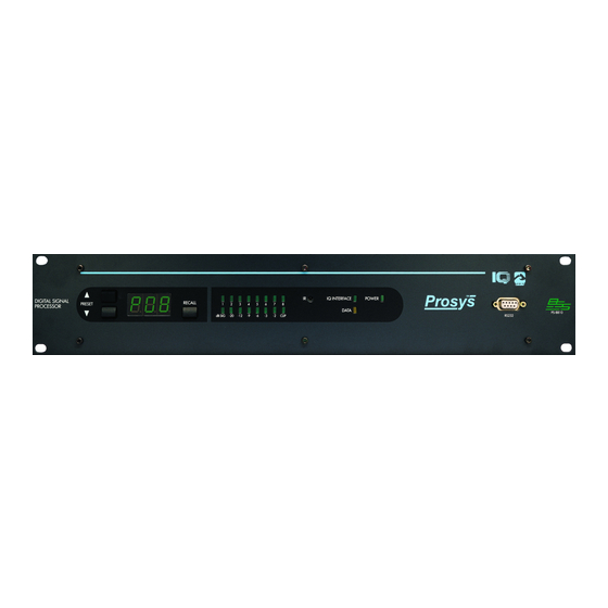
Page 17: Front Panel
PS-8810 DIGITAL SIGNAL PROCESSOR Front Panel a: Power Indicator A green front panel 'Power' indicator lights to show that AC power is being supplied. In addition, the light will blink when an input IR command has been received. b: DATA Indicator An amber front panel data signal presence indicator ('DATA') flashes whenever commands addressed to the BSS PS-8810 are received. -
Page 18: F: Selector Buttons
PS-8810 DIGITAL SIGNAL PROCESSOR Front Panel Selector Buttons and Digital Display When a parameter is changed, a small indicator (A) momentarily lights to show the parameter has been stored in FLASH memory. Another small indicator (B) is illuminated whenever any parameter is varied from its value within the currently selected Preset. -
Page 19: Rear Panel
PS-8810 DIGITAL SIGNAL PROCESSOR Rear panel A: Audio Inputs Three-terminal removable barrier block connectors are provided on the rear panel for balanced analogue audio input. Input Selector Each input has a three-position “M L P” selector switch for mic level, line level, or mic level with phantom power. •... -
Page 20: C: Cobranet Connectors
PS-8810 DIGITAL SIGNAL PROCESSOR Rear panel ® CobraNet Connections and Indicators C: CobraNet Connectors These two RJ-45 connections provide CobraNet access to and from the PS-8810C. This feature is not available on the standard PS- 8810 and this area is covered by a blank plate. The PRIMARY and SECONDARY connectors provide 100Mbit CAT-5 connection to the primary and redundant (secondary) CobraNet networks. -
Page 21: F: Control Port
PS-8810 DIGITAL SIGNAL PROCESSOR Rear panel F: Control Port A male DB37 connector is provided on the rear panel for external monitoring and control of objects within the BSS PS-8810. There are eight digital outputs, eight analogue outputs, eight digital inputs and eight analogue inputs available as well as +5V and +10V for powering external circuits. -
Page 22: Using The Ps-8810
IQ for Windows software. If you are unfamiliar with IQ for Windows software, please refer to the IQ for Windows Help files, visit the BSS Audio website, www.bss.co.uk or the IQ website, www.iqaudiosystems.com, or contact your BSS representative or BSS Technical Support. -
Page 23: Quick Install Procedure
PS-8810 DIGITAL SIGNAL PROCESSOR Quick Install Procedure This procedure is provided for those who are already familiar with the IQ System and would like to install the BSS PS-8810 in the shortest time possible. Less experienced installers or those wishing a full explanation of the installation procedure are encouraged to refer to the hardware installation section. - Page 24 PS-8810 DIGITAL SIGNAL PROCESSOR Quick Install Procedure connector to a 100Mbit dedicated switch. The SECONDARY connector should be wired if a second ‘redundant backup system’ is to be setup. If using just two units then the primaries and secondaries can be connected directly between the units.
-
Page 25: Hardware Installation & Connections
PS-8810 DIGITAL SIGNAL PROCESSOR Hardware Installation & Connections An IQ System with a Host Computer and a BSS PS-8810 The installation of a BSS PS-8810 consists of installing the hardware and configuring the unit via IQ for Windows (IQ Win) software. -
Page 26: Connecting To A Host Computer
PS-8810 DIGITAL SIGNAL PROCESSOR Connections Computer An IQ host computer is a PC running Microsoft Windows 95, 98, Connecting to a ME, 2000 or NT that is used to configure, control or monitor an IQ Host Computer System. Depending upon the design of your IQ System, it may or may not require a host computer during normal operation. -
Page 27: Set The Baud Rate
PS-8810 DIGITAL SIGNAL PROCESSOR PC (RS-232) PS-8810 (RS-232) RS232 Cable Wiring Important: Do not use twisted pair wire for RS232 because it increases crosstalk. Instead, use an untwisted cable or ribbon cable. Set the Baud Rate Baud rate for RS232 serial communication is set using the front panel buttons. -
Page 28: Comms Problems
PS-8810 DIGITAL SIGNAL PROCESSOR Connections Computer When the parameter is adjusted to the desired value, press the RECALL button again to store the setting. The communication parameters of the host computer are set within IQ for Windows software. Please refer to the IQ for Windows Help files for information about setting up communication parameters. -
Page 29: Connecting The Iq Loop
PS-8810 DIGITAL SIGNAL PROCESSOR Connections IQ Loop The ‘IQ Loop’ is a serial communication loop for transmitting IQ Connecting the IQ commands and data between multiple IQ compatible units. It Loop provides excellent flexibility, allowing a IQ Loop ‘loop’ to be wired with either fibre optic cabling or with inexpensive twisted-pair wire. -
Page 30: Ps-8810 In An Iq Loop System
PS-8810 DIGITAL SIGNAL PROCESSOR Connections IQ Loop One of the units must be set as the ‘Master’ for the IQ Loop, this is done by setting its ‘IQ interface’ LED to light using the IQWin software. In order to use more than one PC with the IQ loop the IQNET server software must be used, please refer to the IQNET Server help for more information. -
Page 31: Iq Component Connections
PS-8810 DIGITAL SIGNAL PROCESSOR Connections IQ Loop Three different types of connectors are used for IQ Loop wiring on IQ Component IQ components. These include DIN connectors, RJ-45 connectors, Connections and removable barrier strip plugs. Connection details for these differing types of connectors are found in the following pages. The BSS PS-8810 uses RJ-45 connectors that accept plugs like the one shown below. - Page 32 PS-8810 DIGITAL SIGNAL PROCESSOR Connections IQ Loop RJ-45 Output to Din Input Barrier Block Output to RJ-45 Input Din Output to RJ-45 Input RJ-45 Output to RJ-45 Input www.audiovias.com - 32 -...
-
Page 33: Iq Loop Wiring
PS-8810 DIGITAL SIGNAL PROCESSOR Connections IQ Loop As implemented in the BSS PS-8810 the IQ Loop is a 20-mA IQ Loop Wiring current loop operating at a baud rate of 38.4kbps. The IQ Loop must be unbroken. The IQ Loop connection can use inexpensive twisted-pair wiring (shielded or unshielded). -
Page 34: Audio Wiring
PS-8810 DIGITAL SIGNAL PROCESSOR Connections Audio The BSS PS-8810 has eight mic/line inputs, two main outputs and Audio Wiring eight AUX outputs Three-terminal removable barrier block connectors are provided for the mic/line inputs and main and AUX outputs. About the Audio Three-terminal removable barrier block connectors are provided for the audio inputs. -
Page 35: Suggested Audio Input Gain Control Settings
PS-8810 DIGITAL SIGNAL PROCESSOR Connections Audio Suggested Audio Input Gain Control Settings 0 dBm = 0.775 VRMS with a 600-ohm load, 0 dBV = 1 VRMS, 0 dBu = 0.775 VRMS Balanced Input Balanced sources should be wired as shown below. -
Page 36: Unbalanced Input Wiring
PS-8810 DIGITAL SIGNAL PROCESSOR Connections Audio Unbalanced sources should be wired as shown below. The Unbalanced Input examples are grouped according to whether twin lead shielded Wiring wire or single conductor coax (or twisted pair) wire is used. Unbalanced Audio Input Wiring www.audiovias.com - 36 -... -
Page 37: About The Audio Outputs
PS-8810 DIGITAL SIGNAL PROCESSOR Connections Audio Three-terminal removable barrier block connectors are provided About the Audio for audio output (Figure 6.5). Both main and AUX Audio Outputs Outputs are balanced and can drive 1200 ohms or more to +20 dBu. The two Main outputs and the eight AUX outputs allow the BSS PS-8810 to act as a 24x10 matrix mixer. -
Page 38: Unbalanced Output Wiring
PS-8810 DIGITAL SIGNAL PROCESSOR Connections Audio Unbalanced Output Wiring Unbalanced Audio Output Connections www.audiovias.com - 38 -... -
Page 39: Cobranet Connections
PS-8810 DIGITAL SIGNAL PROCESSOR Connections CobraNet ® ® The CobraNet network carries 8 channels of audio bidirectionally CobraNet via a single cable. Connect the PS-8810C to the CobraNet Connections network using RJ45 terminated standard CAT-5 cable from the PRIMARY connector on the rear of the unit. The PRIMARY connection can either be connected to another PS- 8810 unit or other CobraNet compatible component’s PRIMARY port. - Page 40 PS-8810 DIGITAL SIGNAL PROCESSOR Connections CobraNet ® In order for the system to conform to the stated regulatory requirements, clamp-on ferrites that are shipped with the unit must be attached to the PRIMARY and SECONDARY CobraNet cables. Be sure to double loop the cable in the ferrite. www.audiovias.com - 40 -...
-
Page 41: Control Port Connections
PS-8810 DIGITAL SIGNAL PROCESSOR Connections Control Port Connect any external circuits you plan to use to control and/or Control Port monitor the BSS PS-8810 via the Control Port. The diagram Connections below shows pin assignments for the Control Port. See the Control Port (Section 16.0) for information on the operation of the Control Port, and for examples of wiring circuits to the Control Port connector. -
Page 42: Modem Connection
PS-8810 DIGITAL SIGNAL PROCESSOR Connections Modem Connection The BSS PS-8810 is also modem compatible. The BSS PS-8810 Modem periodically sends out an “AT” command string {ATS0=1} that Connection automatically initializes a connected Hayes compatible modem to its max baud rate and auto-answer mode. The link is non handshaking. - Page 43 PS-8810 DIGITAL SIGNAL PROCESSOR F o r W i n d o w s This section describes how to set up the PS-8810 from within IQ Win software and includes an overview of the various processing functions and associated windows. www.audiovias.com - 43 -...
-
Page 44: Pc Requirements
PS-8810 DIGITAL SIGNAL PROCESSOR 10.0 IQ Win Overview The PS-8810 is configured using IQ Win software. This application enables the setup of all the parameters available to the DSP of the ProSys unit. PC Requirements To run IQ Win successfully a 200Mhz Pentium II (preferably 400Mhz or better) machine with an absolute minimum of 32MB RAM (64MB or more is better) is recommended. -
Page 45: Iq Win Notes
PS-8810 DIGITAL SIGNAL PROCESSOR IQ Win Overview versions of these files that pertain to the same hardware setups can then be scheduled to change using the Schedule function in the File menu and this can even be linked to MIDI Time Code using the MTC Scheduler in the Setup menu. - Page 46 PS-8810 DIGITAL SIGNAL PROCESSOR IQ Win Overview installations. Error reporting can be suppressed if necessary - this is useful in larger systems where there may be too much generation of data. A security system is implemented using a set of passwords to protect almost any aspect of the software’s functionality from unauthorised access or alteration.
-
Page 47: Quick Set Up
PS-8810 DIGITAL SIGNAL PROCESSOR PS-8810 & IQ Win IQ Win software is used to configure the PS-8810. This is a free Quick Set Up download from the IQ Audio Systems web site at www.iqaudiosystems.com. At the time of writing this software is at version 5 and some elements of the interface and functionality may change if a newer version is released. -
Page 48: Processing Functions
PS-8810 DIGITAL SIGNAL PROCESSOR 11.0 Processing Functions Metering & Status Metering IQ Win Input Path Control Window Output Level Meters Audio level meters are provided for each output. The meters sense the audio signal immediately after the audio output processing block. Meter range is from –60 to +20dBu with 0.5dB resolution. -
Page 49: Input Dynamic Cut/Boost Meters
PS-8810 DIGITAL SIGNAL PROCESSOR Processing Functions Metering & Status Input Dynamic Cut/Boost Meters Meters are provided for each Input Processing Section to indicate the overall cut or boost being applied from all signal processing features that affect input gain, including Auto-leveler, Input Compressor, and Automixing. -
Page 50: Dsp
PS-8810 DIGITAL SIGNAL PROCESSOR Processing Functions The DSP processing is divided between four individual DSP’s; two for the input processing and two for the mixing and output processing. • DSP 0 does the processing for input channels 1 through 4 •... -
Page 51: General
PS-8810 DIGITAL SIGNAL PROCESSOR Processing Functions General General Real Time Clock The onboard Real Time Clock tracks day, date, hour, minute and second, and may be set to any date and time desired, or to match that of the computer running IQ for Windows software. The clock is used as a time reference for the Events Scheduling feature. -
Page 52: Interface
PS-8810 DIGITAL SIGNAL PROCESSOR Processing Functions General Interface When activated the PS-8810 acts as the IQ interface ‘master’, allowing itself and other components on the unit’s IQ loop to communicate to a host computer connected via its RS232 port. Note that only one PS-8810 can be the interface on a loop and that each type of IQ component must have a unique IQ address. -
Page 53: Signal Path
PS-8810 DIGITAL SIGNAL PROCESSOR Processing Functions Signal Path Signal Path The PS-8810 is an 8 analogue input/10 analogue output digital signal processor and matrix mixer that also has the capability of routing 8 digital inputs and 8 digital outputs from a CobraNet network when the PS8810C or CobraNet card is used. -
Page 54: Input Path
PS-8810 DIGITAL SIGNAL PROCESSOR Processing Functions Input Path Input Path This panel is accessed by clicking on either the input select buttons or the first object (Input Level/Polarity/Mute) in the Signal Path for the required channel. Input Selector Choose which input channel to view by either pressing the blue or green input channel required or, pick an input from the drop down box. -
Page 55: Input Signal Fader, Muter, And Inverter
PS-8810 DIGITAL SIGNAL PROCESSOR Processing Functions Input Path process box in order to edit its parameters. Input Signal Fader, Muter, and Inverter The output of each of the Input Processing Sections has a fader associated with it prior to the Matrix Mixer. In addition, the Input Processing Section has a muter and inverter. -
Page 56: Input Filters
PS-8810 DIGITAL SIGNAL PROCESSOR Processing Functions Input Filters Input Filters Type The Input Filters provide an array of filter types for any processing need: Low-pass High-pass Low-pass Shelf High-pass Shelf Low-pass EQ High-pass EQ Parametric EQ Frequency All filters are frequency adjustable from 20-20KHz Gain Gain is adjustable from +24dB to –24dB. -
Page 57: Band Eq
PS-8810 DIGITAL SIGNAL PROCESSOR Processing Functions Input Filters Each DSP is capable of 64 filters that must be shared between Input Processing Sections. In addition to preprocessing filtering , there is post-processing filtering and side-chain filtering associated with each gate. Each individual filter can be switched off or the entire processing filter section can be turned on or bypassed. -
Page 58: Post-Processing Filters
PS-8810 DIGITAL SIGNAL PROCESSOR Processing Functions Input Filters High Q filters with gain greater than unity can cause unwanted ringing. This is true for both digital and analogue filters and should be used with great care. Each filter is shown graphically in the larger window and can be controlled by clicking on the filter ‘nodes’... -
Page 59: Input Delay
PS-8810 DIGITAL SIGNAL PROCESSOR Processing Functions Input Delay Input Delay A delay can be added to any of the Input Processing Sections in order to time-equalize the various input signals. Delay is displayed in IQ for Windows software in time, feet, and meters. Control range is from 0 to 100 milliseconds in 20 microsecond steps. -
Page 60: Input Gate
PS-8810 DIGITAL SIGNAL PROCESSOR Processing Functions Input Gate Input Gate The Input Gate feature allows signals above a certain level to pass and attenuates lower level signals. When 'open', the Input Gate passes the input signal un-attenuated. When 'closed', it attenuates the input signal by an amount specified with the Depth control. -
Page 61: Signal Delay
PS-8810 DIGITAL SIGNAL PROCESSOR Processing Functions Input Gate open. Once opened the input must reach a level below the Threshold minus Hysteresis to close. Control range is from 0dB to 12dB in 0.5dB steps Signal Delay Additional delay applied to the input signal, but not to the control key signal. -
Page 62: Auto-Leveler
PS-8810 DIGITAL SIGNAL PROCESSOR Processing Functions Auto-leveler Auto-Leveler The Auto-leveler works in tandem with the Input Gate to compensate for long-term average input levels that vary over time. When the Auto-leveler is enabled, the open state gain of the corresponding Input Gate, normally 0dB, is adjusted dynamically to achieve a desired average output level. -
Page 63: Target Level
PS-8810 DIGITAL SIGNAL PROCESSOR Processing Functions Auto-leveler Target Level Sets the desired average output level. The Auto-leveler will expand input signals below this level and compress input signals above this level. Control range is from -100 to +20dB in 0.5dB steps. Max Gain Sets the maximum gain through the Auto-Leveler. -
Page 64: Input Compressor
PS-8810 DIGITAL SIGNAL PROCESSOR Processing Functions Input Compressor Input Compressor The input compressor provides a means for controlling the dynamic range of input signals. It is a feed-forward type, which performs the compression after the Input Level Meter. The Input Compressor’s effect on input gain is metered by the Input Dynamic Cut/Boost Meter. -
Page 65: Soft Knee (Width)
PS-8810 DIGITAL SIGNAL PROCESSOR Processing Functions Input Compressor Soft Knee (Width) Sets a range in dB around the actual threshold through which the compressor gain is gradually modified from unity to the final compressed gain. Control range is from 0 dB to +20dB in 0.5dB steps. Attack Time Sets the time required for the Compressor to decrease its gain by 20 dB. -
Page 66: Priority Ducking
PS-8810 DIGITAL SIGNAL PROCESSOR Processing Functions Auto-Mixer Automatic mixers allow 'hands-free' mixing that minimises many of Automixer the undesirable effects of using multiple microphones. Applications such as conference rooms, training rooms and boardrooms typically implement many microphones for individual speakers. Simultaneously mixing all microphones with acceptable gain before feedback manually is not possible. -
Page 67: Automixing Group Controls
PS-8810 DIGITAL SIGNAL PROCESSOR Processing Functions Auto-Mixer Automixing Group Controls There are two group controls and two group indicators for this feature: Priority Mix Enable Turns Ducking Priority Mix on and off for the automix group Max Number of Open Mics Sets the max number of open mics within the automix group. -
Page 68: Nom Attenuation
PS-8810 DIGITAL SIGNAL PROCESSOR Processing Functions Auto-Mixer NOM (Number of Open Mics) Attenuation reduces overall system gain as the number of open mics increases beyond one for Attenuation improved gain before feedback. There are three group controls for this feature: Enable Turns NOM Attenuation on and off within an automix group Mode... -
Page 69: Ambient Level Meter
PS-8810 DIGITAL SIGNAL PROCESSOR Processing Functions Auto-Mixer Ambient Level Meter Indicates the calculated ambient level for the automix group. Group Gate Threshold Ambient Offset Sets the amount above the calculated ambient level for the gate threshold for all inputs participating in the automix group. •... -
Page 70: Automix Matrix
PS-8810 DIGITAL SIGNAL PROCESSOR Processing Functions Auto-Mixer Automix Matrix Accessed by pressing the Auto-mix Martian button in the Signal Path window. This window is an interactive overview of all the possible automix routings assignments and priorities. There are three main automix functions;... -
Page 71: Automixing Individual Controls
PS-8810 DIGITAL SIGNAL PROCESSOR Processing Functions Auto-Mixer Automixing Individual Controls There are four individual Input controls: Priority Assigns a relative priority to each channel. Control range is 1 to 8; where 1 is the highest priority and 8 is the lowest priority Depth of Cut Sets the ‘ducked’... -
Page 72: Solo/Mute
PS-8810 DIGITAL SIGNAL PROCESSOR Processing Functions Solo/Mute Solo/Mute The status of the Input and Output channel mutes and solos can all be monitored by pressing the “Solo/Mute” button above the main Signal Path window. From here individual channels can be soloed for preview purposes and muted equally, all solos and mutes can be switched in or out for the Inputs and Outputs separately. -
Page 73: Input/Output Matrix
PS-8810 DIGITAL SIGNAL PROCESSOR Processing Functions Input/Output Matrix Input/Output Matrix The matrix allows routing, soloing, muting, gain adjustment and polarity inversion of the available audio channels through the PS- 8810. This panel is accessed by clicking on the grey area of the 24x10 block in the middle of the Signal Path window. - Page 74 PS-8810 DIGITAL SIGNAL PROCESSOR Processing Functions Input/Output Matrix system and the signal from Input Processing Section B for recording. This panel at top left of the window has two functions; firstly it acts as the overall mute cancel control, the top speaker icon unmuting all the outputs, the bottom all the inputs and the middle both the inputs and outputs simultaneously.
- Page 75 PS-8810 DIGITAL SIGNAL PROCESSOR Processing Functions Input/Output Matrix The CobraNet input channels have the CobraNet logo and are coloured pink. There are no overall channel controls available to these inputs. The crosspoint controls in the Matrix itself enable an amount of signal to be routed using the black level control - control range is from “Off”...
-
Page 76: Output Path
PS-8810 DIGITAL SIGNAL PROCESSOR Processing Functions Output Path Output Path This panel is either accessed by clicking on one of the numbers written in the 24x10 area or by clicking on the Output fader/mute/ polarity icon at the end of the Output processing section. In addition to the output of each of the sixteen Input Processing Sections, the eight CobraNet Inputs are fed to the Matrix Mixer, providing a 24 Input by 10 Output fully independent crosspoint... -
Page 77: Output Section
PS-8810 DIGITAL SIGNAL PROCESSOR Processing Functions Output Section Output Processing Sections Output Section Each of the ten Outputs, (two 'Main' and eight 'AUX)', have independent Output Processing Sections to allow control of the mixed output. Output Processing functions include delay, filters, ambient leveler, limiter, fader, mute, and polarity inverter. -
Page 78: Ambient Leveler
PS-8810 DIGITAL SIGNAL PROCESSOR Processing Functions Ambient Leveler Ambient Leveler The Ambient-Leveler expands the output channel gain to compensate for a sensed ambient level. The ambient level can be sensed from any of the sixteen Input Processing Sections, or the computed ambient level from one of the 32 auto-mix groups. -
Page 79: Program Level Dependent Mode
PS-8810 DIGITAL SIGNAL PROCESSOR Processing Functions Ambient Leveler Added Gain, prevent excessive system gain. Control range is from -80 dB to +20 dB in 0.5dB steps Expansion Ratio Determines how much the gain of the output channel will increase for every increase in the ambient signal level above the Threshold setting. -
Page 80: Output Limiter
PS-8810 DIGITAL SIGNAL PROCESSOR Processing Functions Output Limiter Output Limiter The Output Limiter function provides a means of directly monitoring and controlling peak output level. It is especially valuable for the protection of amplifiers, loudspeakers and other audio equipment. The Output Limiter operates similar to a compressor with an infinite compression ratio, preventing the output level from exceeding the specified Threshold. -
Page 81: Output Select
PS-8810 DIGITAL SIGNAL PROCESSOR Processing Functions Output Select Output Select Each AUX output is individually switchable via the AUX Output Select switches, accessed by clicking on the black Aux boxes in the Signal Path window. The eight rear panel AUX outputs can either be the output of an Output Processing Section or they can be fed from a CobraNet Output. -
Page 82: 12.0 Presets
PS-8810 DIGITAL SIGNAL PROCESSOR 12.0 Presets The BSS PS-8810 has the ability to reconfigure itself with a single command. Thirty-two 'Presets' can be stored and recalled via a variety of means including the front panel, via a Control Port Input, an IR command, or a scheduled 'Event'. For a Preset to be stored, all of the individual controls needs to be set up using IQ Win whilst on-line to the PS-8810, then the 'Store' button pressed and a Preset selected. -
Page 83: 13.0 Scenes
PS-8810 DIGITAL SIGNAL PROCESSOR 13.0 Scenes There are times when only a few objects’ settings need to be changed and this is the function of 'Scenes'. PS-8810 Scenes allow up to 50 objects to be grouped together and changed to a specific state with a single command. -
Page 84: Scene Editor
PS-8810 DIGITAL SIGNAL PROCESSOR Scenes Scene Editor Select the Scene to be edited in the ‘Scene’ box at top, or click on one of the 32 buttons located at the right of the screen. The ‘Controls’ selector allows the type of parameters to be chosen to be narrowed down by selecting either ‘dB’... -
Page 85: 14.0 Events Scheduler
PS-8810 DIGITAL SIGNAL PROCESSOR 14.0 Events Scheduler Different configurations can be triggered at particular times. The BSS PS-8810 has an internal real time clock that can be used to setup a schedule for recalling Presets or Scenes. By using the 'Event Scheduler' to recall unit settings at certain times, the unit can be used in a variety of different ways. -
Page 86: One Time Events
PS-8810 DIGITAL SIGNAL PROCESSOR Events Scheduler One Time Events An Event can be scheduled to occur only once, and the time of the Event can be programmed by choosing 'once'. The exact time of the Event can then be set. Periodic Events If an Event is required at a set rate, the Event editor allows the programming the Event at periodic intervals. -
Page 87: Schedule
PS-8810 DIGITAL SIGNAL PROCESSOR Events Scheduler Schedule The main Event 'View Schedule' button allows viewing of all of the enabled Events for a defined period of time. This ensures that the desired sequence of periodic Events are occurring at the desired times. - Page 88 PS-8810 DIGITAL SIGNAL PROCESSOR CobraNet ® www.audiovias.com - 88 -...
-
Page 89: Explanation
PS-8810 DIGITAL SIGNAL PROCESSOR 15.0 CobraNet ® CobraNet is a technology developed by Peak Audio, Inc. that Explanation allows real time digital audio to be distributed over standard Fast (100Mb) Ethernet hardware. CobraNet allows the PS-8810C to not only have analogue inputs and outputs, but also to provide 8 digital Inputs and 8 digital Outputs from a CobraNet network. - Page 90 PS-8810 DIGITAL SIGNAL PROCESSOR CobraNet ® The Conductor recognizes each device on the network and assigns a transmission position for each bundle of each device. In addition the Conductor sends master clock to each device to ensure that all audio is synchronous. Like a conductor of an orchestra, the Conductor signals the beginning of a synchronous transmission cycle, and then each device sends its bundle(s) in lock step.
-
Page 91: Setup
PS-8810 DIGITAL SIGNAL PROCESSOR CobraNet ® Setup Setup The CobraNet Setup tab allows an overall control of the PS-8810- C’s CobraNet functions. Several labels and information are available: System Name This user defined label indicates the name of the particular PS- 8810C System Description This label is embedded in the CobraNode and indicates the... -
Page 92: Ip Address
PS-8810 DIGITAL SIGNAL PROCESSOR CobraNet ® Setup IP Address The Internet Protocol address that is assigned by the system integrator. Used as a standard part of ethernet networking transmission protocols and works much like a zip/postal code for the unit on the network. Conductor The CobraNet 'Setup' tab indicates information about the status of the Conductor. -
Page 93: Input
PS-8810 DIGITAL SIGNAL PROCESSOR CobraNet ® Input Input The PS-8810C can accept four Bundles from the CobraNet network and route the audio Slots of those Bundles into the processing and mixing of the unit. These four Bundles (RxA, RxB, RxC, and RxD), are assigned Bundle numbers by the Bundle window. -
Page 94: Output
PS-8810 DIGITAL SIGNAL PROCESSOR CobraNet ® Output Output The PS-8810’s eight CobraNet Outputs can be assigned to be transmitted on Slots in one of four CobraNet Bundles. The CobraNet Outputs can accept audio from either the corresponding ‘B’ Input Processing Section or the corresponding AUX Output Processing Section. - Page 95 PS-8810 DIGITAL SIGNAL PROCESSOR CobraNet ® Output The transmit Bundle is assigned in the window and a unique priority can also be assigned for each Bundle. This Bundle Priority is used by the Conductor to assign a transmit position on the CobraNet network.
-
Page 96: External Control
PS-8810 DIGITAL SIGNAL PROCESSOR External Control www.audiovias.com - 96 -... -
Page 97: 16.0 Infrared Remote Control
PS-8810 DIGITAL SIGNAL PROCESSOR 16.0 Infrared Remote Control The BSS PS-8810 has the ability to use an IR remote control such as a programmable remote control device like the Philips Pronto to remotely control the unit. The front panel of the PS-8810 has an IR receiver that can detect IR signals and switch objects based upon a particular received code. -
Page 98: Ir Code Editor
PS-8810 DIGITAL SIGNAL PROCESSOR Infrared Remote Control IR Code Editor IR Code Editor When a particular IR code’s Edit button is pushed, the IR Code Editor window allows selection of objects for inclusion in that IR code. Each selected object can be edited for particular usage. The IR code can also be configured to recall a 'Preset' or a 'Scene'. - Page 99 PS-8810 DIGITAL SIGNAL PROCESSOR Infrared Remote Control Philips Pronto The Philips Pronto IR Remote Controls, TS1000 and TSU2000, Philips Pronto allow access to the PS8810’s IR commands. The Philips Pronto runs configuration programs that may be created on the remote itself or by using the software package ProntoEdit.
- Page 100 PS-8810 DIGITAL SIGNAL PROCESSOR Infrared Remote Control Philips Pronto Each page contains 8 buttons. There are a total of 64 buttons (0- These buttons correspond to the 64 different code # buttons on the IQ Win control page. These buttons will only work if the IQ address of the PS-8810 is set to 1.
- Page 101 PS-8810 DIGITAL SIGNAL PROCESSOR Infrared Remote Control Philips Pronto • Select the button for RC5x. • Enter in 19 for System (19 defines a PS-8810). • Enter the IQ address (0-63) for Command. • Enter the code # (0-63) for Data. Once all of the buttons and windows are set up, save the program as a *.ccf file type.
-
Page 102: Ps8810 Ir Code Format
PS-8810 DIGITAL SIGNAL PROCESSOR PS8810 IR Code Format www.audiovias.com - 102 -... -
Page 103: 17.0 Control Port
PS-8810 DIGITAL SIGNAL PROCESSOR 17.0 Control Port The Control Port provides a means for external monitoring and control of ‘objects’ within the BSS PS-8810. It can be used to turn peripherals on and off, send signals to other system components, receive digital and/or analogue signals from other components, and indicate status of the input gates. -
Page 104: Digital Inputs
PS-8810 DIGITAL SIGNAL PROCESSOR Control Port Digital Inputs (DIN 1-8) These inputs are digital (high or low) only. The inputs are current Digital Inputs driven and will accept voltages up to +25VDC. They switch at approximately +1VDC. They can be used to control one or more objects within the BSS PS-8810. -
Page 105: Room Combine
PS-8810 DIGITAL SIGNAL PROCESSOR Control Port Digital Inputs (DIN 1-8) inverted logic. Multi-valued objects (e.g. gains, thresholds, etc.) can be set to different settings for input transitions from low-to-high and high-to-low. Bump Object(s) Similar to Set Object mode except that rather than setting the object to an absolute value, the specified values are added to the current object values. - Page 106 PS-8810 DIGITAL SIGNAL PROCESSOR Control Port Digital Inputs (DIN 1-8) are to participate in the room combining, individual closure patterns can be programmed to trigger particular Presets. Each combination can be programmed to its own Preset. The example screen shot shows three digital inputs participating in an 8 option room combining scheme.
-
Page 107: Digital Outputs
PS-8810 DIGITAL SIGNAL PROCESSOR Control Port Digital Outputs There are eight digital outputs. Each output may be controlled Digital Outputs manually, configured to indicate the state of a binary object or, configured to indicate whether a particular Preset is loaded. There is one indicator and five controls for each output: •... - Page 108 PS-8810 DIGITAL SIGNAL PROCESSOR Control Port Digital Outputs There are many possible uses for the Control Port outputs. For example, they can be used to turn on auxiliary cooling fans. To do this the output signal might be used to close a relay. The relay would then turn the fans on or off.
-
Page 109: Analogue Inputs (Ain 1-8)
PS-8810 DIGITAL SIGNAL PROCESSOR Control Port Analogue Inputs The Control Port analogue inputs allow a 0 to +10VDC signal to Analogue Inputs be input to allow remote control of continuously variable objects (AIN 1-8) such as faders or filter frequencies. They can also be used to control switched objects (just like the Digital Inputs). -
Page 110: Analogue Outputs
PS-8810 DIGITAL SIGNAL PROCESSOR Control Port Analogue Outputs In addition to the eight Digital Outputs, there are eight Analogue Analogue Outputs Outputs that can be used to provide an output voltage (0 to +10VDC for control). These outputs can reflect a particular analogue object such as a fader, or a switched object and, can be used to provide drive for such things as lighting controls or for a standard digital type output. -
Page 111: Reference Section
PS-8810 DIGITAL SIGNAL PROCESSOR Reference Section www.audiovias.com - 111 -... -
Page 112: 18.0 Technical Information
PS-8810 DIGITAL SIGNAL PROCESSOR 18.0 Technical Information Technical Description Following is a technical description of the operation of the BSS PS- 8810. Audio Input Section Each audio input signal first passes through a balanced filter designed to eliminate RF interference. The RF filters are a balanced network of chokes, ferrite beads, and capacitors that attenuate both common-mode and differential-mode signals above 500 kHz. -
Page 113: Output Section
PS-8810 DIGITAL SIGNAL PROCESSOR Technical Information audio as a 'brick' of data. After the input DSPs have processed the data, they transfer the audio bricks to shared memory. The two output DSPs then retrieve the audio from memory and do the required output processing. - Page 114 PS-8810 DIGITAL SIGNAL PROCESSOR Technical Information • Flash Memory Storage: In addition to storing program code for the control and DSP processors, flash memory provides storage for all nonvolatile data including Presets and setting • IQ Loop: The dual RJ-45 connector allows IN/OUT connection to an IQ loop.
- Page 115 PS-8810 DIGITAL SIGNAL PROCESSOR Technical Information • Control Port: External events can be either generated or monitored via this port and used to control or signal some function within the unit. Sixteen digital outputs, eight digital inputs, and eight analogue inputs provide access to the unit. current-limited voltages (+5V and +10V) are provided to power external circuits Digital Outputs:...
-
Page 116: 19.0 Block Diagram
PS-8810 DIGITAL SIGNAL PROCESSOR 19.0 Block Diagram www.audiovias.com - 116 -... -
Page 117: 20.0 Specifications
PS-8810 DIGITAL SIGNAL PROCESSOR 20.0 Specifications Front Panel Controls: Front-panel switches select IQ Address, Baud Rate, any of 32 user programmable Scenes, and any of 32 user-defined Presets (P01- P32) A 3-position selector switch (mic/line/phantom) and a calibrated Rear-Panel Controls: gain control for each input Connectors: IQ Loop:... - Page 118 PS-8810 DIGITAL SIGNAL PROCESSOR Specifications Power Requirements: 100VAC to 240VAC, 24W nominal Protection: If communication is lost, the unit will continue to function with the last commands received RS232 Data Communication: Baud Rate: Selectable to 19.2K, 38.4K, 57.6K, or 115.2K BAUD Data Format: Serial, binary, asynchronous;...
- Page 119 PS-8810 DIGITAL SIGNAL PROCESSOR Specifications Control Port: Power Supply: +5VDC and +10VDC outputs are provided. The total output current is limited to 1A Outputs: Logic Low: less than 0.1V Logic High: 10V (via internal pull-up) Output Current is limited to 10mA max per pin Inputs: Input Impedance: greater than 50kOhm...
-
Page 120: 21.0 User Notes
PS-8810 DIGITAL SIGNAL PROCESSOR 21.0 User Notes www.audiovias.com - 120 -... - Page 121 PS-8810 DIGITAL SIGNAL PROCESSOR User Notes www.audiovias.com - 121 -...
Need help?
Do you have a question about the Prosys PS-8810 and is the answer not in the manual?
Questions and answers