
Related Manuals for Strand Lighting Wallrack


Summary of Contents for Strand Lighting Wallrack
- Page 1 rack Armoire Gradateurs Wall Manuel d'utilisation Distribué par PANADIFFUSION 84000 AVIGNON tél : 04 90 88 28 98 Revision Level Rev Février 2010 Revision Date...
- Page 2 Informations Générales This equipment operates at voltage levels that are potentially lethal. Do not touch any of the internal parts of the equipment unless you are fully aware of the hazards involved and the precautions to be taken. It is imperative to provide an adequate earth conductor for the rack and load connections.
-
Page 3: Table Of Contents
Wall rack Notice d'emploie Table des Matières Installation.................... 5 Location ................5 Ventilation ................5 Weight................... 5 Dimensions ................5 Installation Procedure ............7 Supply Connections .............. 7 Three Phase ..............7 Single Phase..............8 Load Connections ..............8 RCD Option................. 10 Control Signal Connections.......... -
Page 4: Installation
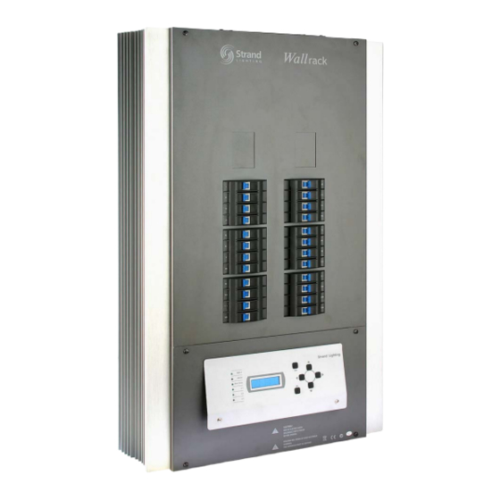
Dimensions Cable entry dimensions are as follows: Power Wiring Top 4 x 25mm holes suitable for conduit(4x2.5kW Wallrack) . Top 3 x 25mm holes suitable for conduit(6x5kW Wallrack) . Top 2 x 25mm holes suitable for conduit(6x2.5kW Wallrack). Control Wiring Bottom 4 x 25mm holes suitable for conduit(4x2.5kW Wallrack) . - Page 5 Wall rack User Manual Wall rack 24x3kw Wall rack 6x 5kw Wall rack 6x3kw User Manual v2.2 Fev. 2010...
-
Page 6: Installation Procedure
Borniers Alimentation Triphasé ou Mono Wall rack s are equipped with terminals f or Single or Three phase plus Neutral and Earth connections. 6 x2.5 kW W al lr ac k 24x2.5kW Wallrack 6x5kW Wallrack Single Phase: 60A Single Phase: 160A Single Phase: 150A... -
Page 7: Single Phase
Wall rack User Manual For the NEUTRAL conductor, we recommend a size of at least 2 x phase conductor size to allow for the harmonic currents generated by phase control dimmers. Mono Phasé Typically wiring for both LIVE L1 and NEUTRAL N should be 25mm for 2.5kW dimmers and 32mm for 5kW dimmers for maximum rack load capacity. - Page 8 Wall rack User Manual Wall 6 x 5kW Wall 6 x 2.8kW rack rack Earthconnections are made directly to the EarthBusbar 24 busbar for 24 ways(12 busbar for 6 ways)clamps for up to 4mm wires are provided in the installation kit are fitted asrequired.
-
Page 9: Rcd Option
Wall rack User Manual Option Inter différentiel 30mA rack is designed to house two 3 phase 30mA RCD (optional) if required. Wall This option only applies when using a 3 phase supply to the dimmer rack it cannot be used on single phase racks. To install the RCD, simply remove the terminals as shown: 24 x 3kW Wall... - Page 10 Wall rack User Manual Wall 6 x 5kW rack Wall 6x2.8kW rack And replace with the 30mA RCDs. Reconnect the power cables as shown below. User Manual v2.2 Jan. 2007...
-
Page 11: Control Signal Connections
Interface de Connections DMX512 - Boutons poussoirs Preset - Panic ..Control connections are made via screw terminals on the plug-in connectors fitted to the Processor Unit PCB Wallrack 24x5kW, Wallrack 6x5kW J2 & J3 : Not used. J4: 18VDC for Architectural control panels. -
Page 12: Processor Set Up
Wall rack User Manual Menu (Setup) Programmation du Processor Wall rack offers a selection of set up and configuration features. These are accessed from the front panel using the six set up keys and LED Display. Menu and setting selections are made with the Up/Down and/or Left/Right keys. -
Page 13: Set Level
Wall rack User Manual Set Level (Envoyer un Gradateur) Press Down button once to go to Set Level menu. Press Right button to enter. Use Up/Down buttons to select all or channels (24 ways: 1- 30, 6 ways: 1- 12). Press the Right button to set the level. Use Up/Down buttons to select Input or an output level of 0-100%. -
Page 14: Preset
Wall rack User Manual Preset (Mémoires) Press Down button twice to go to the Preset menu, press Right button to enter. Use Up/Down buttons to select either Recall, Snap shot or Edit. Use the Right button to enter. For Recall, press Right button to enter. Use Up/Down to select Preset number 1-8, press OK to confirm changes or press Esc to exit without saving any changes. -
Page 15: Address
Wall rack User Manual Addressage DMX Press Down button three times to get to the Address menu. Press Right button to enter. Use Up/Down buttons to select either the Start Address or Patch. Press Right button to enter. For Patch, use Up/Down buttons to select either Mux Patch or Analogue Patch. -
Page 16: Curve
Wall rack User Manual Curve (Courbes) Press Down button four times to go to Curve menu. Press Right button to enter. Use Up/Down buttons to select all or channels (24 ways: 1- 24, 6 ways: 1- 6). Press the Right button to set the curve. Use Up/Down buttons to select Square, Nondim, Lowcut or Linear. -
Page 17: Set Minimum Level
Wall rack User Manual Set minimum level (Intensité minimun) Press Down button five times to go to Minimum Level menu. Press Right button to enter. Use Up/Down buttons to select all or channels (24 ways: 1- 24, 6 ways: 1- 6). -
Page 18: Set Maximum Level
Wall rack User Manual Set maximum level (Intensité de sortie Max) Press Down button six times to go to Maximum Level menu. Press Right button to enter. Use Up/Down buttons to select all or channels (24 ways: 1- 24, 6 ways: 1- 6). -
Page 19: Set Up Menu
Wall rack User Manual Set up menu Press Down button seven times to go to the Set Up menu. Press Right button to enter. Use Up/Down buttons to select either Response time, DMX port, DMX fail, Set Signal Call, Display Version or Set Factory default. Press Right button to enter. -
Page 20: Dmx Port
Wall rack User Manual Priorité des Entrées DMX For DMX port, use Up/Down buttons to select either Merge, Mux A, Mux B or HTP. Press Right button to enter. For the Merge option, you will also need to select the point that Mux B merges with Mux A. -
Page 21: Dmx Fail
Wall rack User Manual Réaction des gradateurs en cas d'Abscence du DMX For DMX fail, use Up/Down buttons to select either Call Preset 1-8, Last Hold or Delay Fade out time. Press Right button to enter. If you selected Call Preset, the DMX state will go to the selected preset when the DMX input fails. -
Page 22: Set Signal Call
Wall rack User Manual Set Signal Call To set the Signal mode, use Up/Down buttons to select either DMX, Preset or Latest Takes Control. Press Right button to enter. Press OK to confirm changes, press again to save or press Esc to exit without saving any changes. -
Page 23: Triac Replacement
Wall rack User Manual Replacement des TRIACs 1. Disconnect the two flat cables. 2. Unplug the 2 red, 2 brown, 4 blue and the green connectors. (Please mark these cables before unplugging them as you need to replace them) 3. Unscrew the 4 choke connections. User Manual v2.2 Jan. - Page 24 Wall rack User Manual 4. Unscrew the PCB clip. 5. Take out the clip as shown. 6. Click the PCB out of the slot. User Manual v2.2 Jan. 2007...
- Page 25 Wall rack User Manual 7. Replace the Triac. 8. Screw back the clip. 9. Tighten the choke connections. User Manual v2.2 Jan. 2007...
- Page 26 Wall rack User Manual 10. Plug the wires back into their original positions. (See note 2) 11. Connect the flat cables. P A N A D I F F U S I O N 27 Fin...
Need help?
Do you have a question about the Wallrack and is the answer not in the manual?
Questions and answers