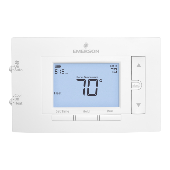
Summary of Contents for Rinnai Brivis 1F83C-11PRBR
- Page 1 Model 1F83C-11PRBR Single Stage Thermostat Programmable Controller Installation Manual Brivis DGH Manual Controller IM...
- Page 2 For continued safety of this appliance it must be installed and maintained in accordance with the manufacturer’s instructions. Read precautions carefully before proceeding with installation. Brivis DGH Manual Controller IM...
-
Page 3: Table Of Contents
TABLE OF CONTENTS Thermostat Applications ..................4 Specifications ......................4 Thermostat Installation Wiring ........................5 Precautions ......................5 Installer Menu.......................6 Test Equipment ....................7 Using The Thermostat Thermostat Overview ..................8 User Menu ......................9 Thermostat Operation ..................9 Thermostat Schedule / Programming ..............10 Troubleshooting ....................10 Contacts ......................12 Brivis DGH Manual Controller IM... -
Page 4: Thermostat Applications
THERMOSTAT APPLICATIONS Maximum Thermostat Applications Stages INDEX Heat/Cool Conventional Gas, Oil, Electric (mV and Maximum Thermostat Installation 24V), Heat Only, Cool Only or Heat/ Thermostat Applications Stages Cool Systems Heat/Cool Wiring Heat Pump (air source or geothermal) Conventional Gas, Oil, Electric (mV and with no Aux. -
Page 5: Thermostat Installation
THERMOSTAT INSTALLATION THERMOSTAT INSTALLATION WIRING WIRING Refer to equipment manufacturer’s instructions for specific system wiring information. After wiring, see INSTALLER MENU for proper thermostat configuration. Wiring table shown are for typical systems and describe the thermostat terminal functions. Terminal Designations Terminal Function Power for Cooling Power for Heating... -
Page 6: Installer Menu
Premium AA alkaline batteries are required when C-wire is not available. When C-wire is available, the batteries provide a back-up source of power (this will maintain the clock in the event of a power outage). 1.) Gas/Elec Switch If the system is a heat pump or electric furnace, the GAS/ELEC Switch must be set to Elec. -
Page 7: Test Equipment
INSTALLER MENU (C0ntinued) Installer’s Menu # Default Setting Description Settings (flashing icons) (Hold Menu 8 Seconds) Early Start (starts heating or On – start early cooling early so your programmed OFF – start at program temperature is reached by the period time programmed time) °F –... -
Page 8: Using The Thermostat
USING THE THERMOSTAT USING THE THERMOSTAT THERMOSTAT OVERVIEW THERMOSTAT OVERVIEW Before you begin using your thermostat, you should be familiar with its features, display and the location/operation of the thermostat buttons and switches. THERMOSTAT BUTTONS AND SWITCHES THE DISPLAY 1.) Fan Switch 10.) Thermostat is protecting the equipment from short cycling (5-minute delay) 2.) System Switch... -
Page 9: User Menu
USER MENU USER MENU To customize thermostat settings, press the Menu button from the home screen. Use the buttons to highlight Settings and press Next. Use Next and Back to navigate through menu items. Press to change the setting. User’s Menu # Default Setting Settings (Press Menu button... -
Page 10: Thermostat Schedule / Programming
THERMOSTAT SCHEDULE / PROGRAMMING THERMOSTAT SCHEDULE / PROGRAMMING Energy Saving Factory Schedule This thermostat is programmed with the energy saving settings shown in the table below for all days of the week. P1/Wake P2/Leave P3/Return P4/Sleep Heating Schedule 6:00 AM - 70°F 8:00 AM - 62°F 5:00 PM - 70°F 10:00 PM - 62°F... - Page 11 TROUBLESHOOTING (C0ntinued) Symptom Possible Cause Corrective Action 1.) System Switch not set to Verify thermostat and system wires are securely attached. Cool 2.) Loose connection to Diagnostic: Set System Switch to Cool and lower thermostat or system setpoint below room temperature. Same procedures 3.) Cooling System requires as diagnostic for “No Heat”...
-
Page 12: Contacts
Tel: 1300 555 545* Fax: 1300 555 655 Monday to Friday, 8.00 am to 5.00 pm EST. *Cost of a local call higher from mobile or public phones. For further information visit www.rinnai.com.au or email enquiry@rinnai.com.au innai has a Service and Spare Parts network with personnel who are fully trained and equipped to give the best service on your innai appliance.


Need help?
Do you have a question about the Brivis 1F83C-11PRBR and is the answer not in the manual?
Questions and answers