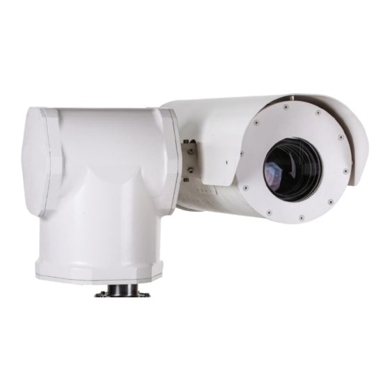
Summary of Contents for Evve Long Range MK Series
- Page 1 Vlierberg 4-06A 3755 BS Eemnes The Netherlands Phone: +31 0 85 0441855 (NL) E-mail: info@evvelongrange.com Web : www.evvelongrange.com MK-Series...
-
Page 2: Table Of Contents
EVVE LONG RANGE ABOUT THIS DOCUMENT ........................... 3 ADDITIONAL INFORMATION & RELATED DOCUMENTS ................. 3 FFC COMPLIANCE ............................2 SUPPORT SERVICES ............................. 2 RETURNS ............................... 2 SHIPMENT ..............................3 SAFETY INSTRUCTIONS ..........................3 1. INTRODUCTION: EQUIPMENT SUPPLIED ..................... 5 2. INSTALLATION ............................6 2.1 INSTALLATION OF THE POWER BOX .................... - Page 3 Operation Manual MK-2000HD. This manual is available from the Evve Long Range website at: www.evvelongrange.com/downloads Copyright 2020 by Evve Long Range B.V. (ELR). ELR has intellectual property rights to technology embodied in the product described in this manual. Evve Long Range and Evve International BV are trademarkt of BOTHA BV.
-
Page 4: Ffc Compliance
This equipment has been tested and found to comply with the limits for a Class A digital device pursuant to Part 15 of the FCC Rules. These limits are designed to provide reasonable protection against harmful interference when the equipment is operated in a commercial environment. This equipment generates, uses, and can radiate radio frequency energy, and, if not installed and used in accordance with the instruction manual, may cause harmful interference to radio communications. -
Page 5: About This Document
SAFETY INSTRUCTIONS IMPORTANT! If the camera needs to be shipped, please use the original packaging material which was designed to protect the product during transportation. If the original packaging is lost or damaged, please order a replacement at ELR. WARNING: Power supplies used with these cameras operate on 115 Vac or 230 Vac. - Page 6 SAFETY INSTRUCTIONS The Evve Long Range products are part of the next generation of Long Range camera systems, ranging from high-definition (HD) to standard-definition (SD) camera positioning systems. The systems are IP (Internet Protocol) based with a full function built-in operating system. Operator functions features are controlled from the On Screen Display (OSD).
-
Page 7: Introduction: Equipment Supplied
POWER BOX & CONNECTION CABLES POWER BOX & CONNECTION CABLES CAMERA HOUSING WITH SUNSHIELD 12 BOLTS (M12 STAINLESS STEEL) & ALLEN KEY SET Installation Manual MK-Series 5/10... -
Page 8: Installation
This chapter covers the general installation and cable requirements of the MK2000HD series. NOTE: Before starting installation: Choose a flat surface or bracket. Have the bolts available. Do NOT power the systems until all devices are connected. CAUTION: The bolts that are used to install the camera must be securely fastened. - Page 9 2.1 INSTALLATION OF THE POWERBOX 2.2 Place a screwdriver flat in te opening of the socket. 2.3 Place the ground (yellow and green) cable in te socket and remove the screwdriver. 2.4 Unscrew the screw at –V and +V. 2.5 Place the blue camera wire in -V. 2.6 Place the brown camera wire in +V.
-
Page 10: Installation Of The Pt Unit
2.2 INSTALLATION OF THE PT UNIT 1. Place the PT on a flat surface in the correct position to mount the bolts. 2. Fasten the M12 bolts and check if the bolts are securely fastened. 3. Remove the connector (be carefull that you don’t damage the wire). Fasten the M12 bolts and check if the bolts are securely fastened. -
Page 11: Connection Of The Camera To The Pt Unit
2.3 CONNECTION OF THE CAMERA TO THE PT UNIT 1. Remove the bolts from the tilt axle. 2. Slide the camera housing on the drive shaft. 3. Secure the bolts on the drive shaft. 4. Connect the power and data cable from the power box to the camera. - Page 12 Vlierberg 4-06A 3755 BS Eemnes The Netherlands Phone: +31 0 85 0441855 (NL) E-mail: info@evvelongrange.com Web: www.evvelongrange.com Installation Manual MK-Series 10/10...


Need help?
Do you have a question about the MK Series and is the answer not in the manual?
Questions and answers