Table of Contents
Advertisement
Quick Links
MoTeC
SDL3 User Manual
Copyright © 2010 – MoTeC Pty Ltd
The information in this document is subject to change without notice.
While every effort is taken to ensure correctness, no responsibility will be taken for the
consequences of any inaccuracies or omissions in this manual.
PN 63037 V 1.2, May 2013
Advertisement
Table of Contents

Related Manuals for Motec SDL3


Summary of Contents for Motec SDL3
- Page 1 MoTeC SDL3 User Manual Copyright © 2010 – MoTeC Pty Ltd The information in this document is subject to change without notice. While every effort is taken to ensure correctness, no responsibility will be taken for the consequences of any inaccuracies or omissions in this manual.
-
Page 2: Table Of Contents
SDL3 User Manual Contents Introduction ................1 Features ....................1 System Overview .................. 3 Typical Devices used with the Dash Logger ......3 Installation ................6 Mounting and Wiring ................6 Connecting Devices ................7 ... - Page 3 Wire Specification ..............51 PC Connection ................. 52 CAN Bus Wiring Requirements ..........53 SDL3 Data Logger to ECU wiring (RS232) ......54 Update Rate Summary ............... 56 Command Line ................... 58 CAN Bus Bandwidth Limit ..............60 ...
-
Page 5: Introduction
ESDL3 - Enclosed Sport Dash Logger The ESDL3 is an enclosed version of the SDL3, providing the flexibility to connect a display suitable for your application or to use as a 'black box' type data logger. It functions in the same way and uses the same software as the SDL3. - Page 6 Calculations including lap times, lap gain/loss, speed and distance, fuel prediction • Monitor active channels—view all channels live • Sensor zeroing • Details editor including event, venue and vehicle details • Extensive Help screens • To access the newest software features you can download the latest version from www.motec.com/downloads...
-
Page 7: System Overview
Introduction Compatibility • MoTeC ECUs: M4, M48, M8, M400, M600, M800 and M880 • MoTeC Accessories: MDD, E888, SLM, PLM, LTC, BR2, PDM, GPS, etc. • Many non-MoTeC devices Required Accessories Refer to Connecting the Dash Logger to a PC •... - Page 8 Digital input or a Speed input. Expanders E888 The SDL3 supports an E888 Expander, 8 x 10 bit thermocouples only. Accessories A BR2 Beacon Receiver may be connected to the Dash Logger, which allows the Dash Logger to calculate lap times for display and to provide lap information for the data analysis software.
- Page 9 MoTeC Introduction small Video Sync Module (VSM) to be connected to an auxiliary output of the Dash Logger and to the audio input of the camera. Lambda Measurement The PLM Professional Lambda Meter measures the air fuel ratio over a wide range of mixtures with fast response time.
-
Page 10: Installation
20 degrees, However the Dash Logger will give good contrast between 0 and 40 degrees. Display reflections should also be considered when determining the mounting angle. The SDL3 uses a 37 pin Autosport connector. See Connector and SDL3 Pin List By Function for full details. Wiring Tips •... -
Page 11: Connecting Devices
Each sensor needs to be connected to the type of input designed to suit that type of sensor. MoTeC devices have the following input types available: • Analogue Voltage Inputs •... - Page 12 Two wire variable resistance pressure sensors Some voltage output sensors can also be used if they can drive the 1000 ohm resistor without causing an error in their reading (e.g. MoTeC Thermocouple Amplifier). Additionally, on/off switch signals may be connected.
-
Page 13: Outputs
Thermatic Fan o Gear Box Oil Pump Note: Devices that consume more than the maximum current (e.g. motors) should be driven via a relay or a MoTeC PDM (Power Distribution Module). Output Specifications Full specifications can be found in Output Characteristics. -
Page 14: Communications
Installation Communications Communications are used to send and receive data from one device to another. There are two communication protocols: RS232 and CAN. Generally older devices use RS232 and newer devices use CAN. CAN (Controller Area Network) Communications This protocol enables communication between all devices connected to the same bus. -
Page 15: Connecting Devices Examples
MoTeC Installation Connecting Devices Examples Device Connect via Remarks Sensors MoTeC supplies datasheets Inputs: The appropriate input with wiring details for all type depends on the sensors via the website sensor type External Buttons for: Wire between Dash Logger Inputs:... -
Page 16: Software Installation
3. When downloading is finished, double click on the file and select run 4. Follow the instructions on the InstallShield Wizard 5. To start the program after installation, click the Dash Manager icon on the desktop or click Start > All Programs > MoTeC > SDL3 > SDL3 Dash Manager... -
Page 17: I2 Data Analysis Software
Version from the Online menu. See Configuration Versions and Updating. i2 Data Analysis Software MoTeC's i2 data analysis software is used to analyse the logged data that has been recorded by the Dash Logger. Any number and combination of graphs, gauges and reports can be analysed simultaneously. - Page 18 Installation * The connection uses IPV6, which can be affected by firewall and anti virus applications. If you have a Dash Logger connected but it is not listed in Discovered Devices, try disabling or uninstalling all anti-virus software. If the Device is 'discovered' without the anti-virus software, you can turn it back on and put in appropriate exceptions to allow the Dash Logger Manager to communicate with the device.
-
Page 19: Configuration
MoTeC Configuration Configuration All aspects of the Dash Logger can be configured, including; which sensor is connected to which input, the calibration of each sensor, what to display and where to display it, what to log and how fast to log it, tacho range, warning alarms, multi stage shift lights, etc. -
Page 20: Channels
All systems within the Dash Logger that generate values must feed one of the channels. Pre-defined Channels MoTeC has defined an extensive list of channels. General Purpose Channels Since the use of all channels cannot be predetermined, a number of general purpose channels have been included for occasions when a suitable predefined channel is not available. - Page 21 MoTeC Configuration These general purpose channels may be required when measuring an uncommon value, or when a general purpose function needs to generate a special output channel. For example, a 3D table may generate an output channel to control a valve of some sort, in which case a general purpose...
-
Page 22: Channel Properties
Configuration Channel Properties Each channel has defined properties, some of which may be modified by the user. Predefining these properties makes the channels easy to use throughout the rest of the software. • Properties that may be modified by the user o Name The channel names (and abbreviations) may be changed if necessary. -
Page 23: Selecting Channels
MoTeC Configuration Selecting Channels There are two methods of selecting channels, either the Category Method or the Search Method. Category Method This method divides all the channels into categories and sub categories, so that the list can be narrowed down to a small list of channels. For example, the ‘Engine Sensors / Cooling’... - Page 24 Configuration Search Method This method lists all channels in alphabetical order and allows a channel to be found either by typing the first few letters of any word in the channel name, or by scrolling through the list. Note: The words may be typed out of order so that ‘Engine Oil Temp’ could be found by typing "temp eng oil"...
-
Page 25: Connections
Configuring Outputs 1. On the Connections menu, click Devices 2. Select device (e.g. SDL3) and then click the Output Pins tab to list all outputs available for this product 3. Select the output and click Change (or double-click the output) 4. -
Page 26: Calculations
Configuration Dash Manager Software on how to update to a new software version to make the latest communication templates available. Calculations The Dash Logger has special and user definable general purpose calculations available. They are set up from the Calculations menu. Special Calculations •... -
Page 27: Functions
FLASH memory that does not require an internal battery to keep it alive. Logging Memory The SDL3 has optional Data Logging upgrades providing 16 MB or 120 MB of logging memory. See Dash Logger Upgrades. Start and Stop Logging Conditions To avoid logging unnecessary data, logging can be started and stopped by user definable conditions. - Page 28 Configuration Logging Setup Files The logging list can be saved and loaded from a file. This allows multiple logging setups to be used. Logging Rate The logging rate sets how often each channel is logged and can be set individually for each channel. The rate at which the values are logged must be fast enough to record all variations in the reading.
- Page 29 MoTeC Configuration The anti-alias filter is implemented by averaging the channel values between logging events. For example, if a channel has an update rate of 1000 Hz and it is logged at 100 Hz then the preceding 10 samples will be averaged each time it is logged.
- Page 30 Configuration Track Map For the i2 Data Analysis software to plot a track map, either a GPS should be connected or a number of separate sensors that will provide the required information. Track Map using GPS Ensure GPS Latitude and GPS Longitude are logged. Track Map using Sensors The following sensors are required and must be logged: •...
-
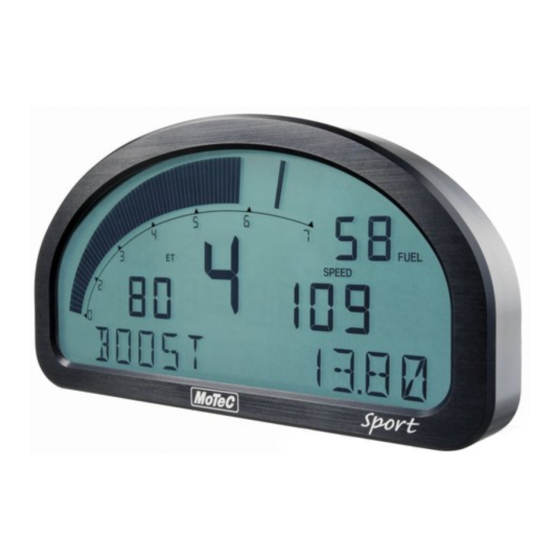
Page 31: Display
MoTeC Configuration Display The Dash Logger display is a high contrast, high temperature, custom made LCD display. The display contains a Bar Graph, three Numeric Displays, a Centre Numeric Display and a Bottom Alpha / Numeric Display. To configure the display •... - Page 32 Configuration The Race display is normally used to display minimal information, e.g. RPM, Lap Time, Fuel Remaining or Laps Remaining. The bottom alpha/numeric display can be used to display additional information as needed. Practice Mode The Practice display is used to display basic information, plus information to help the driver improve lap times, e.g.
- Page 33 MoTeC Configuration Bar Graph The 70 segment bar graph has a user definable range and is typically used as a tacho, however it can be used to display any other value. When used as a tacho it may be configured for up to 19000 RPM.
- Page 34 Configuration for values that are updated periodically. The override values are shown for a programmable period of time. For example, a numeric display could normally show the Running Lap Time (which is continuously updating), then be overwritten by the Lap Time for 10 seconds each time the Lap Time is updated.
-
Page 35: Alarms
MoTeC Configuration Display Formatting Units All display units can be changed to suit the driver preferences, for example, show temperatures in Fahrenheit rather than in Celsius. Note: This is independent of the units used for other purposes. Decimal Places The number of decimal places can be reduced for display purposes, for example the engine temperature is measured to 0.1 °C but is better... -
Page 36: Other Functions
The Dash logger can perform many other functions accessible from the Functions menu including the following: • Shift Lights – to control up to 4 staged shift lights • Shift Light Module – to configure MoTeC's SLM • Engine Log Setup – to set up the engine log... -
Page 37: Operation
MoTeC Operation Operation When operating the Dash Logger, any of the activities of the Online menu of the Dash Logger Manager software can be performed. This requires the PC to communicate to the Dash Logger. Note: All other menu items perform offline activities. -
Page 38: Checking Operation
PC in order to communicate. Dash Manager will show a warning if the versions do not match. Tip: To check the version of Dash Manager, click About MoTeC SDL3 Dash Manager on the Help menu. The firmware version is displayed on the bottom line of the display for 2 seconds when the Dash Logger is powered. -
Page 39: Upgrading The Dash Logger
Note: Ensure you keep passwords secure. The unit needs to be returned to MoTeC for unlocking if the passwords are lost. Other Online Activities Many other activities are accessible from the Online menu including the following: •... - Page 40 Erase Logged Data without unloading o Serial Number to view the Serial and Hardware Number; the Serial Number is required when ordering upgrade passwords, the Hardware Number is for MoTeC internal use o Change Display Mode to switch between Practice, Warm-up and Race mode...
-
Page 41: Appendices
MoTeC Appendices Appendices Specifications Specifications listed as optional are available as upgrades to customise and grow your system. These additional features are activated through a simple password system, at any time when you need it. An overview of the upgrades can be found in Dash Logger Upgrades. - Page 42 Appendices Communications • 2 x CAN with individually programmable CAN bus speeds o Maximum data range 1 Mbit/sec o Recommended terminating impedance 100 ohm • 1 x RS232 Physical • Dimensions 180 x 91 x 18 mm excluding connector • Weight 385 g •...
-
Page 43: Dash Logger Upgrades
MoTeC Appendices Dash Logger Upgrades For the SDL3 Dash Logger the following upgrades are available: Adjustable Backlight Improves readability at night time or at low visibility conditions. This option must be specified at time of purchase. Data Logging 16 MB Allows recording of all input data to a 16 MB internal logging memory. -
Page 44: Characteristics
Appendices Characteristics Input Characteristics Analogue Voltage Inputs Potentiometers Suitable for Voltage output sensors Variable resistance sensors with pull-up resistor Inputs 1—4: 0 to 5.46 V Measure Voltage Range All other Inputs: 0 to 15.0 V Note: Voltages outside this range may affect the readings on other inputs. - Page 45 MoTeC Appendices Analogue Temp Inputs 2 wire variable resistance sensors and some Suitable for voltage output sensors 0 to 15.0 V Measure Voltage Range Note: Voltages outside this range may affect the readings on other inputs. 1000 ohms pull-up to 5 V sensor supply...
- Page 46 Appendices Digital Inputs Switch to 0 V Suitable for Logic signal and open collector device (e.g. Hall Switch) 2200 ohms to 3.3 V Pull-up Resistor 0 to 15 V Voltage Range Positive Trigger 2.4 V max Threshold 0.6 V min Negative Threshold 0.4 V min Hysteresis...
- Page 47 MoTeC Appendices Speed Inputs A 2200 ohm pull-up resistor is connected to 2.7 V Hall mode Switch to 0 V Suitable for Logic signal Open collector device (e.g. Hall Switch) 2200 ohms to 2.7 V Pull-up Resistor 0 to 15 V Voltage Range Selectable between -1.33 V and 4.68 V...
- Page 48 Appendices Period 100 usec Measures period between falling edges Resolution 100 usec Maximum 3.2 sec Pulse Width 1 usec Measures pulse high time Resolution 1 usec Maximum 32 msec Pulse Width 100 usec Measures pulse high time Resolution 100 usec Maximum 3.2 sec...
-
Page 49: Output Characteristics
MoTeC Appendices Analogue Input Sampling 4 times oversampling is scheduled with samples taken every 250 usec, providing measurements every 1 msec. The following inputs are sampled at 250 usec, with microsecond offsets as shown in the table: Offsets 0.0 usec +1.5 usec 0.0 usec... -
Page 50: Sdl3 Pin List By Pin Number
Appendices SDL3 Pin List by Pin Number Name Function Analogue Voltage Input 5 Analogue Voltage Input 6 BAT+ Battery Positive BAT- Battery Negative AUX1 Auxiliary Output 1 AUX2 Auxiliary Output 2 AUX3 Auxiliary Output 3 AUX4 Auxiliary Output 4 E-RX-... - Page 51 MoTeC Appendices Name Function E-RX+ Ethernet Receive + E-TX+ Ethernet Transmit + SPD2 Speed Input 2 DIG1 Digital Input 1 DIG2 Digital Input 2 CAN1L CAN 1 Low CAN1H CAN 1 High Analogue Temp Input 3 Analogue Temp Input 4...
-
Page 52: Sdl3 Pin List By Function
Appendices SDL3 Pin List by Function Name Function Battery Power BAT- Battery Negative BAT+ Battery Positive Analogue Voltage Inputs Analogue Voltage Input 1 Analogue Voltage Input 2 Analogue Voltage Input 3 Analogue Voltage Input 4 Analogue Voltage Input 5 Analogue Voltage Input 6... - Page 53 MoTeC Appendices Name Function Auxiliary Outputs AUX1 Auxiliary Output 1 AUX2 Auxiliary Output 2 AUX3 Auxiliary Output 3 AUX4 Auxiliary Output 4 8 V Sensor Sensor 8 V 5 V Sensor Sensor 5 V 0 V Sensor Sensor 0 V...
-
Page 54: Mounting Dimensions
Appendices Mounting Dimensions SDL3 ESDL3 Note: • All dimensions in [mm] • Ensure product is not stressed when mounted • Dimensions indicate actual product size, allow for clearance when mounting... -
Page 55: Wiring
Appendices Wiring This section provides reference material about the Dash Logger's connector and wiring requirements. Connector 37 pin Autosport connector SDL3 connector #68089 Mating connector Wire Specification Wire Wire to suit Dash Logger connector: 22# Tefzel, Mil Spec : M22759/16-22... -
Page 56: Pc Connection
• Raychem 202K142, • Hellerman 155-42-G Right Angle: • Raychem 222K142, • Hellerman 1155-4-G PC Connection Ethernet Wiring Schematic: SDL3 Ethernet Connector Function Function Ethernet RX+ Ethernet TX+ Ethernet RX– Ethernet TX– Ethernet TX+ Ethernet RX+ Ethernet TX– Ethernet RX–... -
Page 57: Can Bus Wiring Requirements
The preferred cable for the trunk is 100R data cable. • The maximum length of the bus is 16 metres (50 ft) • CAN devices (such as MoTeC Dash Loggers, ECUs etc.) may be connected to the trunk with up to 500 mm (20 in) of twisted wire. -
Page 58: Sdl3 Data Logger To Ecu Wiring (Rs232)
SDL3 Data Logger to ECU wiring (RS232) The following details the methods for connecting the Data Logger to the various MoTeC ECUs via RS232. In all cases this is done using the serial data stream generated by the Telemetry function of each ECU. - Page 59 Cable to convert the logic level signals used by these ECUs into RS232 levels. Using a CIM Module Contact MoTeC for the CIM module drawing for full wiring details. Note: • The data stream to the Data Logger will be interrupted while a PC is...
-
Page 60: Update Rate Summary
50 max * ADL3 CAN comms fast receive 1000 RS232 Communications 200 * General CAN communications 200 * SDL3 Analogue Voltage Inputs SDL3 Analogue Temperature Inputs SDL3 Digital Inputs and Speed Inputs SDL3 RS232 and CAN Communications 50 max *... - Page 61 MoTeC Appendices * RS232 and general CAN communications update rate depends on how frequently the data is sent from the device. Typically the update rate from an M4, M48, M8 or M800 ECU is about 20 times per second using RS232 and...
-
Page 62: Command Line
-c[connection] -d -x -l -e -t -s [config file name] [config file name] (Optional) Fully qualified path to the configuration file. (eg "c:\motec\dash\config\bathurst.d30") Note: the path must included the file extension (eg .d30) Options : Each of the following options can be given as "/[character]" or "- [character]". - Page 63 Perform a “Print Summary” operation. Note: The configuration file must be specified using a fully qualified path including the file extension. (e.g. -p "c:\motec\dash\config\bathurst.d30") Note: There must be a space between -p and configuration file name. (Optional) Perform a “Send Configuration” operation.
-
Page 64: Can Bus Bandwidth Limit
Appendices CAN Bus Bandwidth Limit The total available CAN bandwidth on a single CAN bus is 1 Mbit/sec. The bandwidth used by the total of all devices on a particular CAN bus must not exceed approximately 90% of this value (900000 bits/second) If the total bandwidth required exceeds this specification then some devices should be connected to the second CAN bus. -
Page 65: Comms Error Codes
MoTeC Appendices Comms Error Codes The "Comms CAN x Diagnostic" and "Comms RS232 Diagnostic" channels can be used to diagnose communications problems. Multiple errors are shown by error codes added together. For example: A RS232 error of 9 = parity + overrun. - Page 66 CAN bus transmit warning "VIMCOM" Errors Errors generated by "VIMCOM" devices (SVIM, Dash Loggers). Note: VIMCOM devices are connected via CAN. Dash Logger Errors (SDL3) These errors are generated by the Dash Logger's communications system. FRAMING Incorrect number of samples received.
- Page 67 MoTeC Appendices BAD CONFIG Configuration mismatch between Dash Logger and device. Resend the configuration. NO DATA VIMCOM packets have not been found. Either there is a wiring fault or Dash Logger Connections is setup incorrectly. 2048 WRONG DATA VIMCOM packet has bad length.
-
Page 68: Windows Keyboard Shortcuts
Appendices Windows Keyboard Shortcuts When using a laptop in and around a car, it is often not practical to use a mouse to navigate through the program. Using the keyboard to select options is easier. Main Menu To access the main menu, press ALT + the key for the underlined letter in the menu, followed by the underlined letter of the item in the drop down menu. - Page 69 MoTeC Appendices Selecting an Item in a Window To access the various items in a window, press ALT + the key for the underlined letter of the item of interest, e.g. to select the ‘Flash Light’ item press ALT + F Alternatively use the TAB key to move through the dialog box (use SHIFT + TAB to move backwards).
- Page 70 Appendices Check Box A check box is used to tick on or off a particular option. Press ALT + the key for the underlined letter (F), or use the TAB key to navigate to the Check Box. To select, press SPACEBAR. Group Box The Group box is used to select an item from a group of options.
- Page 71 MoTeC Appendices List Box A list is used to select from a number of options. Press ALT + the key for the underlined letter (M) or use the TAB key to navigate to the List Box. To select, use the arrow keys.
- Page 72 Appendices Tree Structure A Tree Structure is used to select items from a hierarchical list The UP ARROW key moves the cursor up (selects the item above) The DOWN ARROW key moves the cursor down (selects the item below) The RIGHT ARROW key expands; expandable branches indicated by a plus sign (+) The LEFT ARROW key collapses;...
-
Page 73: Glossary
E816 Input/Output Expander E888 Input/Output Expander MoTeC data analysis software i2 Pro MoTeC data analysis software, professional version Ignition EXpander Lambda to CAN module LTCD Lambda to CAN Dual module ECU dedicated to run 2 rotor engines ECU for engines with up to 4 cylinders or up to 2 rotors... - Page 74 PDM32 Power Distribution Module with 32 outputs Professional Lambda Meter Real Time Clock Subaru Diff Controller Sport Dash Logger SDL3 Sport Dash Logger - third generation Strain Gauge Amplifier Shift Light Module Software Update Unit Traction Control Module Versatile Input Module...
- Page 75 MoTeC Notes...
- Page 76 Notes...
Need help?
Do you have a question about the SDL3 and is the answer not in the manual?
Questions and answers