Table of Contents
Advertisement
Advertisement
Table of Contents

Related Manuals for Motec MVCD1000-x


Summary of Contents for Motec MVCD1000-x
- Page 1 Mobile Vicinity Scout (MVS) Operating instruction...
- Page 2 +49 6433 9145-45 motec.info@ametek.com www.motec-cameras.com © Copyright 2018 by Motec GmbH All rights reserved. This document is protected by copyright. It supports the user in the safe and efficient use of the product. Reproductions, translations and duplications in any form, including, but not limited to, require the written consent of the publisher.
-
Page 3: Table Of Contents
System overview ............. 15 Table of Contents Components ..............16 Video control module ..........16 About this instruction ............4 Camera ................ 16 Contact ................5 Monitor ............... 17 Design features ..............5 Type signs ............... 18 Target group of these instructions ........6 Operation .............. -
Page 4: About This Instruction
About this instruction • The operating company must ensure that the operating Thank you for your trust in Motec products! instructions are read and understood by all persons • before starting to work on the product. We develop and produce our products with the greatest care. -
Page 5: Contact
Text Normal flow text • Lists Motec GmbH Steps of action Service This is the general hazard indicator. Oberweyerer Str. 21 It warns of dangers to life and limb. -
Page 6: Target Group Of These Instructions
Installation guidelines and applicable standards. • Technical specifications of the vehicle and the builder of the vehicle body. • Data sheets and operating instructions of the system components. • Motec System Bus (MSB 2.0) specification for systems with CAN communication to the vehicle. -
Page 7: Warranty
• Non-compliance with the instructions. installation/operating instructions. • Unauthorised changes to the system. • Operating mistake. • Neglected maintenance tasks. • Only qualified and trained personnel in consultation with Motec shall be permitted to repair, maintain and adjust the system. -
Page 8: Safety
Safety Intended use Introduction • The Motec MVS System is a driver assistance system can only be operated with a its system limits. This chapter provides an overview of all important safety • The device provides the driver with a 270°/360° all- aspects for the protection of the personnel, and for the safe round view from a bird's-eye perspective. -
Page 9: Inappropriate Use
It is prohibited to use components which are defect and therefore jeopardise the safety of the system! • The Motec MVS is not suitable for the protection of persons in the sense of the applicable standards and guidelines for machines and vehicles (Machinery Directive 2006/42 / EU, DIN EN ISO 13849 and ISO 26262). -
Page 10: Residual Risks
Residual risks Folge • Tree branches or other objects above the cameras are Residual hazards may occur under the following not recorded! In this case, the use of the rear-view circumstances: mirrors or the assistance of a banksman is mandatory! •... -
Page 11: Presentation Of Warning Signs
Presentation of warning signs DANGER Pictogram are used in these instructions to indicate The signal word DANGER indicates an imminent risk. Non- warnings. The warnings are introduced by signal words that compliance leads to serious injuries or death. express the extent of the warning or hazard. •... -
Page 12: Safety And Warning Labels On The System Components
Safety and warning labels on the system • Prior to driving, the driver must proceed with a visual components inspection and a functional test before using the system. • Before the installation of the system components and Information and symbols, such as safety labels and signs, during their operation, compliance with the applicable attached to the system components must be observed. -
Page 13: System Description
System description Camera system The Mobile Vicinity Scout (MVS) is a camera system The system generates one image of one vehicle side, using designed especially for utility vehicles. It provides the driver 3 cameras (270° system) or 4 cameras (360° system). with a clear, seamless 270°... - Page 14 Additional sensors As an option, up to 12 ultrasonic sensors can be connected to the system in conjunction with the MVCU1300-1 control unit. Objects detected by the ultrasonic sensors are displayed as coloured dynamic overlays in the top view. A (pre) warning of objects outside the field of view of the cameras is possible via the ultrasonic sensors if the detection range of the ultrasonic sensors is greater than the calibration range of the cameras shown.
-
Page 15: System Overview
System overview Fig. 2: System overview MVS... -
Page 16: Components
The 180° angle of view and the small design enable adaptation to very different vehicle and visibility situations. Fig. 3: MVCD1000-x / MVCD1001-x • 270° systems use three cameras. The video control unit processes the images delivered by •... -
Page 17: Monitor
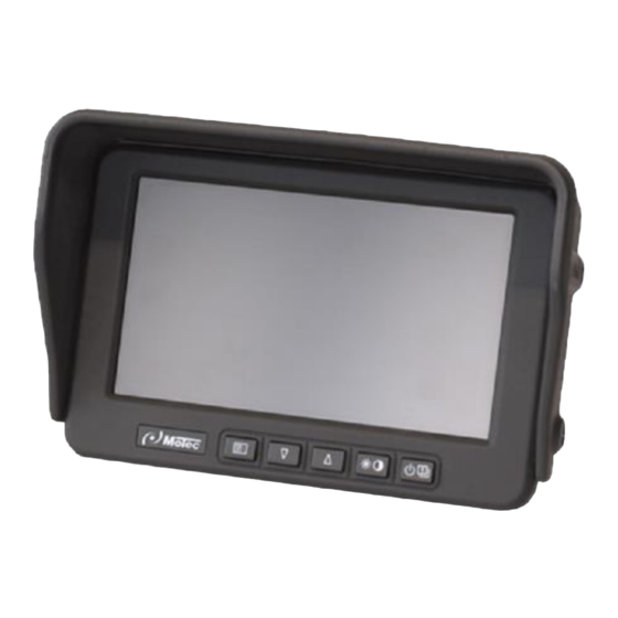
Monitor Depending on the system configuration, the monitor is available in two models: System Monitor 360° or 270° MD3071A-V system Vertical monitor alignment (portrait format) 270° system MD3071A Horizontal monitor alignment Fig. 5: MD3071A (landscape format) Fig. 6: MD3071A-V The 7'' monitor displays the image calculated by the video control unit. -
Page 18: Type Signs
Type signs Fig. 8: Cable ifentification (example) Match code Article number Batch identification (week of production/year) A shrink tube is used to attach the cable identification to ensure, it cannot be lost. Fig. 7: System components type sign (example) Manufacturer’s address Match code Article number CE mark... -
Page 19: Operation
Operation Switching on the system • The driver is always responsible for the vehicle and the 1. Turn on the ignition of the vehicle. system. The system will now boot up until the image is • Prior to driving, the driver must proceed with a visual displayed. -
Page 20: Split Screen Views
Split screen views The video control unit has four control inputs that can be configured at random. A particular display mode can be assigned to each control input. In addition to the top view, individual cameras can also be displayed in a split screen view or as a full screen. For this purpose, the control inputs are connected to the corresponding signals from the vehicle’s electrical system (e.g., reverse gear, indicators, etc.). -
Page 21: Ultrasound Sensors
Ultrasound sensors As an option, the MVS system can be supplemented with 12 ultrasonic sensors. This way, the system will receive a warning if objects are in the field of view of the cameras. If the detection range of the ultrasonic sensors is larger than the calibration range of the cameras, the system can also warn of objects outside the field of view of the cameras. -
Page 22: Troubleshooting
Troubleshooting Hardware Behaviour/malfunction Possible cause Corrective action System not starting. Power supply not available. Turn on power supply. Check fuse, replace as required. Power supply cable defective. Replace cable. Video control unit defective. Replace video control unit. Video control unit is not activated. Activate the power supply. -
Page 23: Malfunctions During Operation
Malfunctions during operation Behaviour/malfunction Possible cause Corrective action Blue monitor screen No video signal on monitor, loose Check cable connection between connector, monitor cable defective. video control unit and monitor, replace defective cables. Check the connector for tight fit, tighten the union nuts of the connector on the video control unit hand-tight, and latch flap into place on the side of the monitor... - Page 24 Behaviour/malfunction Possible cause Corrective action Part of the image is Attachment of the affected camera Check camera bracket for tight fit. shaking in the top view is loose. Ask a certified service partner to check the settings. If necessary, recalibrate the system. Image is blurred Protective film on monitor and/or Remove protective film.
- Page 25 Behaviour/malfunction Possible cause Corrective action The desired partial image System settings not correct. Ask a certified service partner to mode is not displayed check the settings. If necessary, recalibrate the system. Switch-over signal not available. Check the external signals (CAN/control leads) of the vehicle. Ask a certified service partner to check the settings.
-
Page 26: Ultrasound Sensors
Ultrasound sensors Behaviour/malfunction Possible cause Corrective action Objects in the detection Incorrect alignment of the sensors. Check and correct alignment. range of the ultrasonic sensors are not shown Evaluationn unit of MVCU1300 Ask a certified service partner to defective. check the system, and if necessary, have it repaired. - Page 27 Behaviour/malfunction Possible cause Corrective action A permanent warning of Permanently installed objects in the Remove objects. If this is not the ultrasonic sensors is detection area of the sensors possible, adjust the dead range of the sensor. displayed in the overlay Ask a certified service partner to check the system, and if necessary, have it repaired.
-
Page 28: Maintenance
Maintenance Cleaning the monitor • DANGER Use a clean, dry cloth to wipe off fingerprints and dust. • Do not use cleaning fluids, antistatic spray or solvents High voltage! Risk of fatal injuries! such as benzine, paint thinner or other commercially High currents in battery-powered systems can lead to available chemicals. -
Page 29: Disposal And Environmental Protection
Disposal and environmental protection Disposal of the packaging • Packaging was used to protect the product during the transport. All materials used are environmentally friendly and recyclable. • Dispose of the packaging in an environmentally friendly manner. • Ask the dealer or the municipal waste disposal authority for possible disposal of the packaging in an environmentally friendly and appropriate way. -
Page 30: Index
Index Operation ..............19 About this instruction ............. 4 Applicable documentation ..........6 Personal protective equipment must be worn .... 12 Presentation of warning signs ........11 Contact ................5 Residual risks ............. 10 Declaration of Conformity ..........6 Design features ............. 5 Safety ................ - Page 32 Motec GmbH +49 6433 9145-0 Oberweyerer Straße 21 +49 6433 9145-45 65589 Hadamar-Steinbach motec.info@ametek.com GERMANY www.motec-cameras.com...
Need help?
Do you have a question about the MVCD1000-x and is the answer not in the manual?
Questions and answers