Table of Contents
Advertisement
Quick Links
Advertisement
Table of Contents

Related Manuals for Marport Trawl Explorer


Summary of Contents for Marport Trawl Explorer
- Page 1 Trawl Explorer Service Manual...
-
Page 3: Table Of Contents
Contents | ii Contents Legal....................4 History...................................4 Copyright..................................5 Disclaimer..................................5 Introduction and Presentation............6 Introduction................................6 Applications.................................7 Safety Guidelines..............................8 Description.................................. 9 Firmware................................9 Technical Specifications..........................9 Main Parts..............................10 Operational Mode Indicator........................13 Installation Steps..............................14 Sensor Configuration..............15 Installing Mosa2..............................15 Connecting the Sensor to Mosa2........................16 Sounding Modes..............................18 Configuring the Uplink, Up and Down Settings.................. - Page 4 Adding the Sensor to the Receiver..................45 Configuring the Sensor Settings..................... 46 Configuring the Sensor Display on Scala/Scala2..................48 Installation..................52 Installing a Trawl Explorer on the Trawl.....................52 Servicing and Maintenance.............55 Interference Check..............................55 Spectrum Analyzer Display....................55 Checking Noise Interference....................56 Checking Noise Interference....................
-
Page 5: Legal
Trawl Explorer | V5 | Legal Legal History 05/09/17 First release New topic: • About Time Variable Gain on page 22 • Canceling the Ringing on page 35 • Frequency Plan on page 84 03/09/18 • Appendix B: Examples of Installations for a Target Strength Calibration... -
Page 6: Copyright
Marport. “Marport ”, the Marport logo and Software Defined Sonar are registered trademarks of Marport. All other brands, products and company names mentioned are the trademark and property of its respective owners only. Marport is a division of Airmar Technology Corporation. -
Page 7: Introduction And Presentation
Tip: Click Marport logo at the bottom of pages to come back to the table of contents. Introduction Marport’s Trawl Explorer is your eye on the fishing gear. This sounder can be placed on your trawl headrope or tunnel in order to send useful information to the wheelhouse. -
Page 8: Applications
Trawl Explorer | V5 | Introduction and Presentation Applications This is an example of data received from a Trawl Explorer sensor and displayed in Scala/Scala2. Trawl Explorer display from the trawl headrope Sea bottom Fish Target strength Trawl opening... -
Page 9: Safety Guidelines
Install and use this product in accordance with this user manual. Incorrect use of the product may cause damage to the components or void the warranty. Only qualified Marport dealers can do maintenance and repairs on internal components of the sensors. -
Page 10: Description
Trawl Explorer | V5 | Introduction and Presentation Description Firmware There are three versions of the Trawl Explorer. Each version has a different firmware (called NBTE) and different features. NBTE V1 NBTE V2 NBTE V3 Name of firmware FIRM121 FIRM126... -
Page 11: Main Parts
Trawl Explorer | V5 | Introduction and Presentation Beamwidth Beamwidths for uplink pings: Beamwidth @ 35 kHz @ 50 kHz @ 60 kHz -3dB 46° 40° 30° Beamwidths for up and down pings: Beamwidth @ 125 kHz @ 160 kHz... - Page 12 Trawl Explorer | V5 | Introduction and Presentation Exploded View 1. Transducer 2. End cap 3. PCBA 4. Batteries 5. Sensors PCBA Connectors 1. Uplink (C) 6. Water-switch 2. Uplink LED 7. Up (B) 3. Down LED 8. Down (A) 4.
- Page 13 Trawl Explorer | V5 | Introduction and Presentation On the transducer, up and down sounders are written with the letters A (down) and B (up). On older sensors, down sounder is marked by a circle. | 12...
-
Page 14: Operational Mode Indicator
Trawl Explorer | V5 | Introduction and Presentation Operational Mode Indicator Indicators from the transducer State Situation Operation Charging Charger plug is Batteries are charging. No light. connected. Running Sensor is in water or After an initialization phase, activated with jumper. -
Page 15: Installation Steps
Trawl Explorer | V5 | Introduction and Presentation Installation Steps Click an installation step to jump directly to the corresponding section. Note: You can customize the display of data on Scala/Scala2 at any time. | 14... -
Page 16: Sensor Configuration
Trawl Explorer | V5 | Sensor Configuration Sensor Configuration Learn how to configure Trawl Explorer sensor settings. Note: This guide refers to the following versions of Mosa2: 02.03. If you use another version, the visual interface and options may vary. -
Page 17: Connecting The Sensor To Mosa2
Trawl Explorer | V5 | Sensor Configuration c) In the terminal, enter sh /Volumes/Marport-Mosa2/MosaPatchForMavericks.sh d) When prompted, enter the administrator password. e) Close the terminal. f) Open Mosa2 to check if the script has worked. If Mosa2 does not open, it means the script has not worked. - Page 18 Trawl Explorer | V5 | Sensor Configuration 4. Open Mosa2, then wait a few seconds for the sensor to be recognized. When it appears on the discovery page, click Results The sensor configuration page is displayed. Troubleshooting: If the sensor is not detected by Mosa2, the issue might come from the short-range wireless connection of the computer.
-
Page 19: Sounding Modes
Trawl Explorer | V5 | Sensor Configuration Sounding Modes The sensor can send pings according to three different sounding modes. Down 1 Sensor sends pings towards down direction (1) only. You can see fish going into the trawl. Pings are sent quicker than with the other modes, so more data is received, which enables a better horizontal resolution. -
Page 20: Configuring The Uplink, Up And Down Settings
Trawl Explorer | V5 | Sensor Configuration Configuring the Uplink, Up and Down Settings You can configure different settings for uplink, down and up soundings. Before you begin The sensor is connected to Mosa2. About this task Remember: Always click Apply after you change a setting and make sure there is a green... - Page 21 Trawl Explorer | V5 | Sensor Configuration Note: The range influences the display of echogram images. When the range is short, data can arrive quicker, which gives better quality images. But the bigger the range is, the lesser the image quality is, because data arrives slower. If you are using Down 1 + Up or...
-
Page 22: Target Strength
Ping frequency is an important setting for the calibration of the sensor. If you change ping frequency on a sensor calibrated for target strength, it will have to be returned to a Marport sales' office for target strength calibration. Target Strength... -
Page 23: About Time Variable Gain
Trawl Explorer | V5 | Sensor Configuration • 40 log: focus on individual targets. • 30 log: compromise between the two above settings. For V1 and V2 versions of sensors: • In TVG Coefficient, enter between 0.500 and 0.520 to have approximately the equivalent of 20 log , 0.75 for 30 log or 1 for 40 log. -
Page 24: Configuring Measurement Sending Sequence And True Mode
3. From Option True Mode, select a sequence from True Mode Option. • Select Config1 (default): this is the more appropriate sequence for a Trawl Explorer. • Or select Config3 if you use the True mode display on echograms in Scala/Scala2. - Page 25 Trawl Explorer | V5 | Sensor Configuration | 24...
-
Page 26: Configuring The Noise Floor
Trawl Explorer | V5 | Sensor Configuration Configuring the Noise Floor Even when the sensor is in a silent environment, a small level of noise is detected. You need to measure this level of noise so that the sensor ignores it when operating, otherwise it could have effects on the echogram. -
Page 27: Changing The Transducer And End Cap Orientation
Trawl Explorer | V5 | Sensor Configuration 5. Click Apply and make sure there is a green check mark Changing the Transducer and End Cap Orientation For V1 version of the sensor, you need to change the orientation of the transducer and end cap of the sensor to correctly receive pitch and roll data. - Page 28 Trawl Explorer | V5 | Sensor Configuration 1. Using a 1.5 mm Allen key, remove the four screws holding the retainers that are on the side of PCBA where all the cables are connected. 2. Carefully disconnect the up (B), down (A), uplink (C) and uplink LED cable from the PCBA using needle nose pliers.
-
Page 29: Changing The End Cap Orientation
Trawl Explorer | V5 | Sensor Configuration 1. Turn to 90° the transducer as shown on the picture. 2. With an Allen key, screw back the transducer. 1. Before / 2. Turn 90° to the right / 3. After / 4. Card slot 4. - Page 30 Trawl Explorer | V5 | Sensor Configuration 2. Turn the end cap. 1. Turn to 90° the end cap as shown on the picture. 2. Ensure the slots for the screws in the end cap are facing those in the housing.
-
Page 31: Selecting A1 Board Orientation
Trawl Explorer | V5 | Sensor Configuration 1. Replace the protective tape. 2. Install 2 new main o-rings and 2 backup o-rings on the end cap and transducer as illustrated (cross-section). Inspect and fully clean the o-ring grooves. 3. Check that all seals in the bottle are clean and lubricated. -
Page 32: Calibrating The Sensor For Target Strength Value
Trawl Explorer | V5 | Sensor Configuration 1. Vertical 2. Standard (horizontal) Calibrating the Sensor for Target Strength Value For V3 version of the sensor, you need to calibrate the sensor to offset the variability of the sensor transducer and of sound transmission. The aim is to have all sensors displaying the same target strength value (echogram color) for a given target. - Page 33 > Expert Mode and enter the password copernic. 4. Click the tab Trawl Explorer and click Up or Down Ping Calibration. 5. Check that the target strength is the one applicable to your target. In this example, it is -39 dB (target strength value of a ping pong ball of 39 mm diameter).
- Page 34 Trawl Explorer | V5 | Sensor Configuration 1. Ping pong ball / 2. Side lobes (tank walls) /3. Bottom 8. From the bottom of the screen, click Calibrate. Note: If the sensor is not correctly placed, you may have an error message asking you to correct the pitch and/or roll angle.
- Page 35 Trawl Explorer | V5 | Sensor Configuration The sensor sends 1 ping to check if the calibration settings are correct in comparison to the target strength set (e.g. -39 dB). If they are correct, calibration settings are saved. If calibration settings are not correct, check: •...
-
Page 36: Canceling The Ringing
1. From Mosa2, click Menu > Expert Mode and enter the password copernic. 2. From the tab Trawl Explorer, click Ringing Down. 3. Place the sensor in a large tank or in your office and click Emit 10 Ping Down. - Page 37 Trawl Explorer | V5 | Sensor Configuration 5. From the graph, click and drag red line points above the gray and yellow curves: a) The red line should follow the same curve. b) The 4th point can be placed at the point where the yellow and gray lines go under the noise floor (green line).
-
Page 38: Configuring The Uplink Power
Trawl Explorer | V5 | Sensor Configuration Configuring the Uplink Power You can increase the uplink power of the sensor to increase the power of the signal transmitted. It is useful if you have interferences or if the sensor is far from the vessel. -
Page 39: Updating The Sensor
• Or, click Copy to clipboard then press Cmd + V on a word processor like Pages to paste the contents. 6. Marport offices only: To add the test on the DealerWeb: a) Click Copy to clipboard. b) From the DealerWeb, click Sensors > A1. -
Page 40: Downloading The Firmware
The board ID is written on Mosa2. 4. From the firmware section: a) In the first column select Narrow Band Trawl Explorer 400Hz V2 or V3. a) From the second column, select the version of the firmware. Latest is on top. -
Page 41: Exporting Sensor Configuration Settings For Record Keeping
Trawl Explorer | V5 | Sensor Configuration Note: On tablet computers, Browse only search for *.a1f files in the Downloads folder. Information on the sensor firmware is displayed. 5. Click Apply. 6. Wait for the updating to be complete. 7. Connect and disconnect the sensor to a charger to restart the sensor and validate the update. -
Page 42: Exporting Sensor Configuration Settings For The Receiver
• Or, click Copy to clipboard, then press Cmd + V on a word processor like Pages to paste the contents. 5. Marport offices only: you need to add the contents of this file on the DealerWeb. a) Click Copy to clipboard. - Page 43 Trawl Explorer | V5 | Sensor Configuration • Click Save to file to download the XML file on the computer. • Or, click Copy to clipboard, then press Cmd + V on a word processor like Pages to paste the contents.
-
Page 44: System Configuration And Display
Adding the Sensor to the Receiver You need to add the Trawl Explorer to the receiver in order to display sensor data on Scala/Scala2. About this task The Trawl Explorer is compatible with the following M3/M4/M5/M6 receiver and Scala versions:... - Page 45 Trawl Explorer | V5 | System Configuration and Display 3. Click the tab Add from Marport Sensor Config Utility. 4. Click Browse and select the XML file. Information about the sensor is displayed. 5. Select a node from the list on the left. Nodes in green are already used.
-
Page 46: Adding The Sensor Manually
Configure Receiver. 4. From the left side of the receiver page, click Sensors. 5. From Product Category, select Trawl Explorer. 6. From Product Name, select Narrow Band Trawl Explorer with Target Strength (V1)/(V2)/(V3) (choose accordingly to Firmware on page 9 installed). -
Page 47: Configuring The Sensor Settings
Trawl Explorer | V5 | System Configuration and Display 8. Click Add Sensor. The sensor is added to the receiver and displayed on the left side of the screen. The configuration page is displayed. Configuring the Sensor Settings Important: Make sure the settings you enter here are the same as in Mosa2. - Page 48 200 Hz margin before and a 400 Hz + 200 Hz margin after the Trawl Explorer. So if the Trawl Explorer sensor is given the frequency 44000 Hz, the uplink frequency of the previous sensor has to be at 43800 Hz or lower, and the uplink frequency of the sensor after has to be at 44600 Hz or higher.
-
Page 49: Configuring The Sensor Display On Scala/Scala2
Trawl Explorer measurements are displayed in the control panels, under Sensors Data / Mx. Data title should be Trawl Explorer followed by the node where the Trawl Explorer was placed when added to the system. Data displayed (e.g. depth, temperature, pitch & roll) depend on the firmware installed. - Page 50 Trawl Explorer | V5 | System Configuration and Display For more details about display in Scala/Scala2, please refer to Scala/Scala2 user guide. Figure 1: Example of Trawl Explorer display If using Down only mode and if the trawl opening configured for the sensor is under 20 meters, the sounding range automatically changes to 20 meters if the distance to the bottom becomes lower than 20 meters (1).
- Page 51 To display the target strength: a) From the top left corner of the echogram, right-click the Trawl Explorer name and select Display Target Strength. b) Hover the mouse over the echogram.
- Page 52 Trawl Explorer | V5 | System Configuration and Display 6. Deactivate the Customize mode when you have finished customizing pages: click Menu > Customize again. | 51...
-
Page 53: Installation
Trawl Explorer | V5 | Installation Installation Learn how to install Trawl Explorer sensors on the trawl gear. Installing a Trawl Explorer on the Trawl We recommend to install the sensor on the headrope in order to see the trawl opening and fish entering the trawl. - Page 54 Trawl Explorer | V5 | Installation 1. Place sensor (1) at the centre of the net's headrope (2), facing the vessel. 2. Install a double-mesh piece of netting (3) to stabilize the sensor. 3. Buoys (4) on either sides provide a level platform for the unit during trawling operations.
- Page 55 Trawl Explorer | V5 | Installation Tunnel To install the sensor on the trawl tunnel, install it on a location corresponding to nodes 7, 8 or 9 on the image below: The installation procedure is the same as the one for the headrope.
-
Page 56: Servicing And Maintenance
Trawl Explorer | V5 | Servicing and Maintenance Servicing and Maintenance Read this section for troubleshooting and maintenance information. Interference Check You can check if there is noise interfering with the reception of signals. Spectrum Analyzer Display The following picture explains the main parts of the spectrum analyzer page on Scala/Scala2. -
Page 57: Checking Noise Interference
Trawl Explorer | V5 | Servicing and Maintenance Checking Noise Interference You can use the spectrum analyzer to check the noise level of the hydrophones and check for interference. About this task Spectrum Analyzer Display on page 55 for details about the spectrum analyzer display. -
Page 58: Checking Noise Interference
Trawl Explorer | V5 | Servicing and Maintenance 6. To see the maximum, mean and real time measures of noise level at a specific frequency, select Marker on the left side of the screen and move the mouse over the graph. - Page 59 Trawl Explorer | V5 | Servicing and Maintenance 5. The spectrum analyzer is displayed. You can display up to 6 spectrum analyzers at the same time. Below is an example of a page with two spectrum analyzers. The FFT plot shows three levels of noise in dBV: 1.
- Page 60 Trawl Explorer | V5 | Servicing and Maintenance • RealTime: the latest highest level of noise (dBV) recorded and its frequency. • Max: the highest level of noise recorded since the beginning of the spectrum and its frequency. 8. Check that there is more than 12 dBV between the maximum noise level (dark blue line) and the average noise level (cyan line) on the peak of sensor frequencies.
-
Page 61: Charging The Sensor
14. Right-click the IP address of the receiver in the status bar and click Stop Spectrum. Charging the Sensor Charge the sensor at any battery level with either Marport Basic Sensor Charger or Marport Medusa II Multi-charger. About this task The sensor uses lithium-ion batteries. -
Page 62: Maintenance
Read this section to learn best practices for maintaining the sensor. Only an approved Marport dealer can access the internal unit. Warranty will become void if anyone other than an approved dealer tries to do internal maintenance duties on the sensor. -
Page 63: Cleaning The Sensor
Trawl Explorer | V5 | Servicing and Maintenance Cleaning the Sensor You need to regularly clean the sensor for proper performance. Wash the sensor with fresh water before you charge or store it. Regularly check that the sensor is clean. If not: •... -
Page 64: Maintenance Checklist
Trawl Explorer | V5 | Servicing and Maintenance Maintenance Checklist We recommend you to follow this maintenance schedule for better performance and to avoid any trouble with the equipment. Before use • Check that all attachment equipment are not worn or torn. Replace when appropriate. -
Page 65: Replacing Parts
Trawl Explorer | V5 | Servicing and Maintenance Replacing Parts Qualified Marport technicians can remove and replace the following parts if they are damaged. Removing and Putting Back the Housing You need to remove the housing and tube around the bottle to get access to the components inside the bottle. -
Page 66: Replacing The Batteries
For this task you need the following tools: O-ring lubricant (Molykote 55 o-ring grease) About this task Only qualified Marport technicians can do this task. Standard Trawl Explorer sensors have two batteries, mini Trawl Explorer sensors only have one. Procedure 1. Remove the old batteries. | 65... - Page 67 Trawl Explorer | V5 | Servicing and Maintenance 1. Remove the tape protecting the components. 2. Remove the two batteries (one battery for a mini) from the internal housing and disconnect them from the battery adaptor board. Trawl Explorer Mini Trawl Explorer...
- Page 68 Trawl Explorer | V5 | Servicing and Maintenance A. End cap / B. Transducer 1. Main o-ring / 2. Backup o-ring | 67...
-
Page 69: Replacing The Shoulder Bolts
Trawl Explorer | V5 | Servicing and Maintenance Replacing the Shoulder Bolts Before you begin For this task you need the following tools: Allen key: 1/8" Philips Flat head Tweezers O-ring Anti-seize screwdriver screwdriver lubricant or 5/64" (Molykote 55 Allen key... - Page 70 Trawl Explorer | V5 | Servicing and Maintenance 1. Fully clean the surface and hole from debris (with a swab or Q-tip) and inspect the surface for burrs or pitting. 2. Put new lubricated o-ring crushes inside each hole of the shoulder bolts.
-
Page 71: Replacing The Pressure Sensor
Trawl Explorer | V5 | Servicing and Maintenance Replacing the Pressure Sensor Replacing the Pressure Sensor Before you begin Before installing, check on the end cap that there is this pressure-relief symbol. It shows that your sensor has a pressure-relief spring. - Page 72 Trawl Explorer | V5 | Servicing and Maintenance 1. Remove the tape protecting the components. 2. Using a 1.5 mm Allen key, remove the four screws holding the retainers that are on the side of PCBA where all the cables are connected.
- Page 73 Trawl Explorer | V5 | Servicing and Maintenance 1. Screw / 2. Spring / 3. Metal ring / 4. Pressure sensor / 5. Small o-ring (1mm thick) / 6. Adapter ring (metal, must be installed with grove-side up) / 7. Large o-ring (1.5mm thick, may stay in the bottom of the hole when pressure sensor is removed) / 8.
- Page 74 Trawl Explorer | V5 | Servicing and Maintenance 1. Put the pressure sensor cables through the hole in the internal housing. 2. Connect the cables to the white connector according to the order on the picture (view of side with clips upward).
-
Page 75: Replacing The Temperature Sensor
Trawl Explorer | V5 | Servicing and Maintenance 5. Click Download Depth Programmer. The XML file is downloaded in the Downloads folder. 6. Connect the sensor to Mosa2. 7. From Mosa2, click Menu > Expert Mode and enter the password copernic. - Page 76 Trawl Explorer | V5 | Servicing and Maintenance Procedure 1. Remove the retainers around the PCBA to get access to the connectors. 1. Remove the tape protecting the components. 2. Using a 1.5 mm Allen key, remove the four screws holding the retainers that are on the side of PCBA where all the cables are connected.
-
Page 77: Replacing The Transducer
Trawl Explorer | V5 | Servicing and Maintenance 1. Replace the o-ring seals with new lubricated seals. 2. On the new temperature sensor cables, strip the end of each cable and crimp pins to each stripped cable. Tip: If you do not have the necessary tools to do... - Page 78 Trawl Explorer | V5 | Servicing and Maintenance Allen keys: Needle Silicon glue O-ring 1.5 mm, 1/8" nose pliers lubricant (Molykote 55 o-ring grease) About this task Only qualified Marport technicians can do this task. Procedure 1. Disconnect components. 1. Using a 1.5 mm Allen key, remove the four...
- Page 79 Trawl Explorer | V5 | Servicing and Maintenance 1. Remove the two screws maintaining the transducer with the 1/8" Allen key. 2. Remove the transducer and its cables. 3. Install the new transducer. 1. The LED cable must face directly the internal housing and go through the hole dedicated to this cable.
- Page 80 Trawl Explorer | V5 | Servicing and Maintenance 1. Replace the protective tape. 2. Install 2 new main o-rings and 2 backup o-rings on the end cap and transducer as illustrated (cross-section). Inspect and fully clean the o-ring grooves. 3. Check that all seals in the bottle are clean and lubricated.
-
Page 81: Troubleshooting
The firmware has the wrong board ID. • Check that the last set of numbers in the name of the firmware file corresponds to the board ID of your sensor. If not, Marport offices need to download the correct firmware file from the DealerWeb. -
Page 82: Data In Scala/Scala2 Is Wrong
Trawl Explorer | V5 | Servicing and Maintenance If the sensor is not detected by Mosa2, the issue might come from the short-range wireless connection of the computer. 1. Close Mosa2. 2. Click the short-range wireless symbol in the top-right corner of the menu bar while holding the Shift (#) + ALT (#) keys on your Mac's keyboard. -
Page 83: Echogram Is Fixed And Blue
1. Check that the name of the sensor on the top left corner of the echogram is Trawl Explorer. 2. If not, from Trawl Explorer sensor data, click + hold Range of Sonar Data and drag it to the page. -
Page 84: Support Contact
Trawl Explorer | V5 | Servicing and Maintenance Support Contact You can contact your local dealer if you need maintenance on your Marport products. You can also ask us at the following contact details: FRANCE ICELAND Marport France SAS Marport EHF 8, rue Maurice Le Léon... -
Page 85: Appendix
Trawl Explorer | V5 | Appendix Appendix Frequency Plan It is important to carefully plan the setup of your sensors before adding them to the system. You can create a table with a list of frequencies and complete it when you add sensors. - Page 86 Trawl Explorer | V5 | Appendix C-4/CH5 42700 C-4/CH6 43300 C-5/CH1 42024 C-5/CH2 41690 C-5/CH3 41285 C-5/CH4 41060 C-5/CH5 42900 C-5/CH6 43400 C-6/CH1 39062 C-6/CH2 39375 C-6/CH3 39688 C-6/CH4 40000 C-6/CH5 40312 C-6/CH6 40625 C-7/CH1 38906 C-7/CH2 39219 C-7/CH3 39531...
- Page 87 Trawl Explorer | V5 | Appendix Frequencies and intervals The diagrams below show the bandwidth of the different types of Marport sensors and intervals you must respect when adding other sensors. Figure 2: PRP sensors (e.g. Catch sensor, Trawl Speed, Spread sensor...) Example: If the frequency of the sensor is 40kHz, there should be no sensors between 39.9-40kHz...
- Page 88 Trawl Explorer | V5 | Appendix Examples of frequency allocations • We recommend to allocate frequencies between 34 and 56 kHz for wideband hydrophones and between 41 kHz and 44 kHz for narrowband hydrophones. • Echosounders are usually placed around 38 kHz, make sure to allow enough distance with them.
- Page 89 Trawl Explorer | V5 | Appendix | 88...
-
Page 90: Appendix B: Examples Of Installations For A Target Strength Calibration
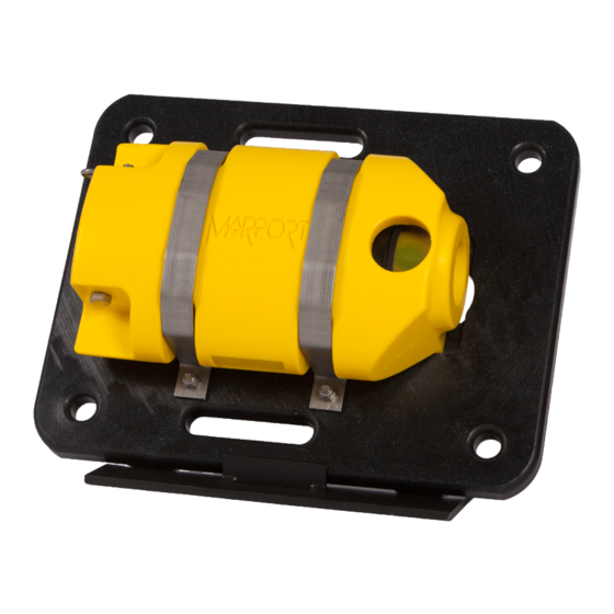
Trawl Explorer | V5 | Appendix Appendix B: Examples of Installations for a Target Strength Calibration Support for sensor Figure 6: Example of support Figure 7: Example of support | 89... - Page 91 Trawl Explorer | V5 | Appendix Ping pong ball Figure 8: Fishing line passes through the ball and is fixed with glue. Figure 9: Example of installation with counterweights. | 90...
- Page 92 Trawl Explorer | V5 | Appendix 1. 50 cm 2. 1 m 3. Counterweight | 91...
-
Page 93: Index
Index | 92 Index Battery life Export Beamwidth Firmware Boat code Error message Update Frequency Calibrating Frequency bandwidth Installation examples Frequency plan Target Strength Channel code Charger Housing Maintenance Installing Plugging Removing Cleaning Compatibility Mosa Operating System Indicators Config Read Installation Contact Installation steps... - Page 94 Index | 93 Noise floor System requirements Noise Interference Target strength Operational modes Technical specifications Option True Mode, See Measurement sending sequences Transducer orientation Changing Selecting Trawl opening Parts TVG (Time Variable Gain) PCBA connectors Pings Pulse length Uplink power Range Receiver Water ingress...
Need help?
Do you have a question about the Trawl Explorer and is the answer not in the manual?
Questions and answers