Nilfisk-Advance GD 5 Battery Service Manual
Hide thumbs
Also See for GD 5 Battery:
- Instructions for use manual (13 pages) ,
- Specifications (4 pages) ,
- Instructions for use manual (11 pages)

Related Manuals for Nilfisk-Advance GD 5 Battery


Summary of Contents for Nilfisk-Advance GD 5 Battery
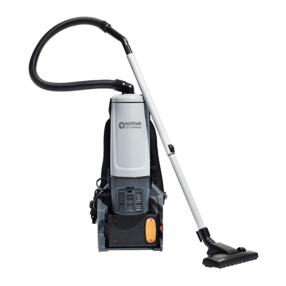
- Page 1 26.06.2017 GD 5 Battery Service manual ENGLISH GD 5 Battery variants: EU, UK, CH, AUS, CN, US.
- Page 2 Index A. Preface B. Technical data Troubleshooting D. Service / repair Spare parts Electrical diagram...
- Page 3 Preface In this manual you will find A fault in the equipment Technical information sheets are a supplement to the spare the essentials you need to can have a number of causes. parts list until a follow-on publi- know when repairing the GD5 Chapter C Troubleshooting cation.
- Page 4 Safety issues Observe national safety directives and regulations For your own safety for the electrical engineer- ing trade, in particular: IEC 60335-2-69 EN 60335-2-69 DIN VDE 105 part 1: operation of electrical power installations. DIN VDE 0701/0702: repair, modification and Repairs should only be made testing of electrical installa- by someone who has re-...
- Page 5 Technical data GD 5 Battery specifications - all variants...
- Page 6 Troubleshooting TIP: Use a Multimeter to measure voltage and Machine does not start ohm. Check: - Is the battery working correctly (i.e. no yellow or red LED on)? - Is there power on the battery (light in green LED when pushing battery button)? Is power (≥30V) coming through Is power Replace...
-
Page 7: Table Of Contents
Service / repair 0. Disassembly 1. Change motor unit 2. Change switch + cord 3. Change PCB 4. Change battery connector 5. Change battery lock... -
Page 8: Disassembly
Disassembly WARNING: The electric section of the machine TIP: Unless otherwise contains live components. stated a TX20 bit is nee- Always disconnect the battery before disassembly. ded for the screws. Loosen the on/off switch to not be connected to the harness; use a TX10 bit (fig.1). -
Page 9: Change Motor Unit
Change motor unit WARNING: The electric section of the machine contains live components. Always disconnect the battery before disassembly. Disassemble the unit following guide in previous section D.0. Unscrew the cable relief (fig.1) and disconnect the motor wires from the PCB (fig.2+3). - Page 10 Change motor unit WARNING: The electric section of the machine contains live components. Always disconnect the battery before disassembly. Loosen the latches fixing the motor unit (fig.4). Unscrew and remove the outer co- ver (fig.5) and the motor cover (fig.6). Make notice of how the motor is turned.
- Page 11 Change motor unit WARNING: The electric section of the machine contains live components. Always disconnect the battery before disassembly. Unscrew the cable relief (fig.7). Make notice of the cable position in the cable guide and pull out the cable. Assemble the machine backwards. Take spe- cial notice that the motor housing is placed cor- rectly (fig.8).
-
Page 12: Change Switch + Cord
Change switch + cord WARNING: The electric section of the machine contains live components. Always disconnect the battery before disassembly. Disassemble the unit following guide in previous section D.0. Unscrew the cable relief (fig.1) and disconnect the switch wires from the PCB (fig.2). -
Page 13: Change Pcb
Change PCB WARNING: The electric section of the machine contains live components. Always disconnect the battery before disassembly. Disassemble the unit following guide in previous section D.0. Making good notice of how the wires are connected to the PCB disconnect all wires and unscrew the PCB;... -
Page 14: Change Battery Connector
Change battery connector WARNING: The electric section of the machine contains live components. Always disconnect the battery before disassembly. Disassemble the unit following guide in previous section D.0. Unscrew the brackets holding the battery connector (fig.1). Disconnect the wires from the battery connector on the PCB (fig.2 + 3). -
Page 15: Change Battery Lock
Change battery lock WARNING: The electric section of the machine contains live components. Always disconnect the battery before disassembly. Disassemble the unit following guide in previous section D.0. Unscrew the battery lock (fig.1). Change the battery lock and reas- semble the machine. - Page 16 Spare parts Cassette and electronics...
- Page 17 Spare parts Motor parts...
- Page 18 Spare parts Container parts...
- Page 19 Spare parts Harness...
- Page 20 Electrical diagram GD5 Battery wiring diagram...
Need help?
Do you have a question about the GD 5 Battery and is the answer not in the manual?
Questions and answers