Table of Contents
Advertisement
Installation and Maintenance Instructions
CONTENTS
SAFETY CONSIDERATIONS . . . . . . . . . . . . . . . . . 1, 2
GENERAL . . . . . . . . . . . . . . . . . . . . . . . . . . . . . . . . . 2-4
INSTALLATION . . . . . . . . . . . . . . . . . . . . . . . . . . . . 5-13
Step 1 - Unpack and Inspect Units . . . . . . . . . . . . 5
Step 2 - Position the Unit . . . . . . . . . . . . . . . . . . . . 5
Step 3 - Install Ductwork . . . . . . . . . . . . . . . . . . . . . 6
Step 4 - Connect Piping . . . . . . . . . . . . . . . . . . . . . . 6
Step 5 - Complete Electrical Connections . . . . . . 7
Step 6 - Position and Connect Controller . . . . . . 7
WIRING
ACB (Auxiliary Control Board) Interface . . . . . . . 13
START-UP . . . . . . . . . . . . . . . . . . . . . . . . . . . . . . . . . . 13
Pre-Start Check . . . . . . . . . . . . . . . . . . . . . . . . . . . . . 13
System Operation Check . . . . . . . . . . . . . . . . . . . . 13
MAINTENANCE . . . . . . . . . . . . . . . . . . . . . . . . . . . 13
INDOOR UNIT ADDRESSING . . . . . . . . . . . . . 13-14
Wireless Remote Controller (40VM900001) . . . . . 13
Programmable Controller (40VM900003) . . . . . . . 14
TROUBLESHOOTING . . . . . . . . . . . . . . . . . . . 15, 15
Replacement Parts. . . . . . . . . . . . . . . . . . . . . . . . . 16
APPENDIX A - DIP SWITCH SETTINGS . . . . . . . 17
APPENDIX B - FAN CURVES . . . . . . . . . . . . 18, 18
SAFETY CONSIDERATIONS
Improper installation, adjustment, alteration, service,
maintenance, or use can cause explosion, fire, electrical shock,
or other conditions which may cause death, personal injury or
property damage. The qualified installer or agency must use
factory authorized kits or accessories when modifying this
product.
Follow all safety codes. Wear safety glasses, protective
clothing, and work gloves. Use quenching cloth for brazing
operations. Have fire extinguisher available. Read these
instructions thoroughly and follow all warnings or cautions
included in literature and attached to the unit. Consult local
building codes and the current editions of the National
Electrical Code (NEC) ANSI/NFPA (American National
Standards Institute/National Fire Protection Association) 70.
For Canada, refer to the current editions of the Canadian
Electrical Code CSA (Canadian Standards Association) C22.1.
Understand the signal words - DANGER, WARNING,
and CAUTION. DANGER identifies the most serious hazards,
Manufacturer reserves the right to discontinue, or change at any time, specifications or designs without notice and without incurring obligations.
Catalog No. 16-40VMV001-01
Variable Refrigerant Flow (VRF) Systems
Page
Printed in U.S.A
Form 40VM-2SI
Vertical AHU Fan Coil for
which will result in severe personal injury or death.
WARNING signifies hazards that could result in personal
injury or death. CAUTION is used to identify unsafe practices,
which could result in minor personal injury or product and
property damage.
Recognize safety information. This is the safety-alert
symbol (
). When this symbol is displayed on the unit and in
instructions or manuals, be alert for the potential of personal
injury. Installing, starting up, and servicing the equipment can
be hazardous due to system pressure, electrical components,
and equipment location.
WARNING
Electrical shock can cause personal injury and death. Shut
off all power to this equipment during installation. There
may be more than one disconnect switch. Tag all
disconnect locations to alert others not to restore power
until work is completed.
WARNING
When installing the equipment in a small space, provide
adequate measures to avoid refrigerant concentration
exceeding safety limits due to refrigerant leak. In case of
refrigerant leak during installation, ventilate the space
immediately. Failure to follow this procedure may lead to
personal injury.
WARNING
DO NOT USE TORCH to remove any component. System
contains oil and refrigerant under pressure.
To remove a component, wear protective gloves and
goggles and proceed as follows:
a. Shut off electrical power to unit.
b. Recover refrigerant to relieve all pressure from
system using both high pressure and low
pressure ports.
c. Traces of vapor should be displaced with
nitrogen and the work area should be well
ventilated. Refrigerant in contact with an open
flame can produce toxic gases.
d. Cut component connection tubing with tubing
cutter and remove component from unit. Use a
pan to catch any oil that may come out of the
lines and as a gage for how much oil to add to
the system.
e. Carefully unsweat remaining tubing stubs
when necessary. Oil can ignite when exposed to
torch flame.
Failure to follow these procedures may result in personal
injury or death.
Pg 1
40VMV012-054
2-17
Replaces: 40VM-1SI
Advertisement
Table of Contents

Related Manuals for Carrier 40VMV012


Summary of Contents for Carrier 40VMV012
-
Page 1: Table Of Contents
40VMV012-054 Vertical AHU Fan Coil for Variable Refrigerant Flow (VRF) Systems Installation and Maintenance Instructions CONTENTS Page which will result in severe personal injury or death. WARNING signifies hazards that could result in personal SAFETY CONSIDERATIONS ....1, 2 injury or death. -
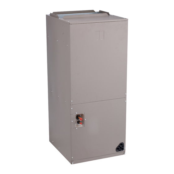
Page 2: General
GENERAL CAUTION The 40VMV vertical AHU (air-handling unit) is equipped with a DC motor. The unit features dual drain spouts so it can DO NOT re-use compressor oil or any oil that has been be mounted vertically or horizontally, and is ideal for closet exposed to the atmosphere. - Page 3 Table 2 — 40VMV Physical Data UNIT 40VMV 208/230-1-60 POWER SUPPLY (V-Ph-Hz) 12,000 18,000 24,000 30,000 36,000 48,000 53,500 COOLING CAPACITY (Btuh) 13,500 21,000 27,000 34,000 40,000 54,000 60,000 HEATING CAPACITY (Btuh) INDOOR FAN MOTOR DC Motor Type Input (W) INDOOR COIL Number of Rows Fin Spacing (fins/in.)
- Page 4 AIR SUPPLY REFRIGERANT PIPE (GAS SIDE) REFRIGERANT PIPE (LIQUID SIDE) DRAIN PIPE RIGHT SIDE AIR RETURN FRONT LEFT SIDE 40VMV UNIT SIZE 012-030 036-054 NOTE: All dimensions shown in inches. Fig. 2 — 40VMV012-054 Dimensions...
-
Page 5: Installation
INSTALLATION Step 2 — Position the Unit Step 1 — Unpack and Inspect Units Units DANGER packaged for shipment to avoid damage during normal transit and handling. It is the receiving party’s responsibility to inspect Units must not be installed where they may be exposed to the equipment upon arrival. -
Page 6: Step 3 - Install Ductwork
bottom of the trap and outlet should also be 3 inches. See Fig. 4. IMPORTANT: If the unit is installed in the ceiling, be sure that the ceiling grid is supported separately from the unit. The ceiling grid must not be supported by any part of the unit, grille, or any associated wiring or piping work. -
Page 7: Step 5 - Complete Electrical Connections
• Before insulating the suction and liquid refrigeration Table 4 — 40VMV Electrical Data pipes, perform pressure and leak tests. For details, see POWER SUPPLY the outdoor unit installation manual. Insulating both 40VMV UNIT SIZE suction and liquid refrigerant pipes is required. MOPD •... -
Page 8: Option/Extensions Of Communication
— XT1-2 — Terminal Block ---------- Optional Component or Field Wiring Fig. 5 — 40VMV012-054 Typical Wiring Diagram OPTION/EXTENSIONS COMMUNICATION WIRING To extend control wiring or make terminal connections, use the PQ connection wire supplied in the accessory kit and follow the steps below. - Page 9 If for any reason it is not possible to buy communication Fig. 9. wires from Carrier, connect the indoor unit side of the communication wires using the connector provided with the accessories as shown in Fig. 11-13.
- Page 10 Connector on indoor unit Connector in accessory kit Communication cable in field Fig. 11 — Connecting the Communication Cable to Indoor Unit to Outdoor Unit Using the Supplied Connector...
- Page 11 Note: 24v DC Power Touch screen outdoor unit Centralized controller wired controller HA HB Indoor unit 1# Indoor unit 2# To No.1 indoor To No.2 indoor Main MDC To outdoor Indoor unit 3# To No.3 indoor To No.4 indoor To Sub.MDC Indoor unit 4# Wired controller Note: Power from IDU...
- Page 12 Note: 24v DC Power Touch screen outdoor unit Centralized controller wired controller HA HB Indoor unit 1# Indoor unit 2# Indoor unit 3# Indoor unit 4# wired controller Note: Power from IDU HA HB Indoor unit 5# Indoor unit 6# Network Resistor Maximum wiring length L1+L3 </= 3937 ft.
-
Page 13: Acb (Auxiliary Control Board) Interface
ACB (Auxiliary Control Board) Interface 3. While the system is in operation, check the following on outdoor unit: ACB interface is a dry contact board, it can output up to four signals controlling devices. Please refer to Fig. 14 for a. -
Page 14: Non-Programmable Controller (40Vm900002)
Click TEMP. UP or TEMP. DOWN to change 00 to the desired address as shown in Fig. 17. Then press OK to confirm and exit the setting interface. AUTO TEMP COOL 1 – MODE S ETTING 2 – FAN S PEED S ETTING CLOCK HEAT HOUR... -
Page 15: Troubleshooting
3. Press TEMP. UP or TEMP. DOWN to choose the 4. Press BACK twice or wait 30 sec. to automatically exit address you want to set, see Fig. 19. Press MENU/OK to the parameter settings menu. send this address to the IDU. TROUBLESHOOTING Figure 20 shows the LED display panel. -
Page 16: Replacement Parts
Table 6 —Troubleshooting ERROR DESCRIPTION POSSIBLE CAUSES POSSIBLE SOLUTIONS System is in cooling or fan only mode and All units should be in cooling mode for system to heating signal is received from a unit on the stay in cooling mode. system. -
Page 17: Appendix A -Dip Switch Settings
APPENDIX A —DIP SWITCH SETTINGS There are 2 DIP switches on the main board. Figures A and B show the settings for each parameter controlled by a switch. Switches are shown in the default settings. 1 2 3 4 POSITION 1, 2 — NOT USED POSITION 1 —... -
Page 18: Appendix B - Fan Curves
0.40 L-speed 0.20 L-speed 0.20 M-speed 0.00 0.00 1000 AIRFLOW (cfm) AIRFLOW (cfm) Fig. A — 40VMV012 Fan Curves Fig. C — 40VMV024 Fan Curves 1.00 1.00 Upper Limit of ESP Upper Limit of ESP 0.80 0.80 H-speed 0.60 0.60... - Page 19 1.00 1.00 Upper Limit of ESP Upper Limit of ESP 0.80 0.80 H-speed H-speed 0.60 0.60 M-speed M-speed 0.40 0.40 L-speed L-speed 0.20 0.20 0.00 0.00 1000 1100 1200 1300 1400 1000 1200 1400 1600 1800 2000 AIRFLOW (cfm) AIRFLOW (cfm) Fig.
- Page 20 © Carrier Corporation 2017 Manufacturer reserves the right to discontinue, or change at any time, specifications or designs without notice and without incurring obligations. Catalog No. 16-40VMV001-01 Printed in U.S.A. Form 40VM-2SI Pg 20 2-17 Replaces: 40VM-1SI...
Need help?
Do you have a question about the 40VMV012 and is the answer not in the manual?
Questions and answers