Table of Contents
Advertisement
Quick Links
Visit www.carrier.com
Installation, Start-Up, and Operating Instructions
SAFETY CONSIDERATIONS .....................................................1
RECEIVING AND INSTALLATION ..........................................2
CHECK EQUIPMENT ..................................................................2
PROVIDE UNIT SUPPORT .........................................................2
Roof Curb ............................................................................2
Slab Mount ..........................................................................2
Ground Mount .....................................................................2
FIELD FABRICATE DUCTWORK.............................................2
PROVIDE CLEARANCES ........................................................2-3
RIG AND PLACE UNIT.......................................................3, 6-7
CONNECT CONDENSATE DRAIN ...........................................7
INSTALL FLUE HOOD ...............................................................7
INSTALL GAS PIPING.............................................................7-8
INSTALL DUCT CONNECTIONS .......................................8, 10
INSTALL ELECTRICAL CONNECTIONS.........................11-13
High-Voltage Connections ................................................11
Special Procedures for 208-V Operation..........................11
Control Voltage Connections ............................................12
Standard Connection..........................................................12
Heat Anticpator Setting.....................................................13
Transformer Protection......................................................13
PRE-START-UP ..........................................................................13
START-UP..............................................................................13-22
MAINTENANCE....................................................................22-26
REFRIGERANT SYSTEM..........................................................26
QUICK REFERENCE GUIDE....................................................27
TROUBLESHOOTING ..........................................................28-30
START-UP CHECKLIST............................................................31
NOTE TO INSTALLER - Before the installation, READ
THESE INSTRUCTIONS CAREFULLY AND COMPLETELY.
Also, make sure the User's Manual and Replacement Guide are
left with the unit after installation. the furnace is NOT to be used
for temporary heating of buildings or structures under construc-
tion.
SAFETY CONSIDERATIONS
Installation and servicing of air-conditioning equipment can be
hazardous due to system pressure and electrical components. Only
trained and qualified personnel should install, repair, or service
air-conditioning equipment.
Untrained personnel can perform basic maintenance functions of
cleaning coils and filters. All other operations should be performed
by trained service personnel. When working on air-conditioning
equipment, observe precautions in the literature, tags and labels
attached to the unit, and other safety precautions that may apply.
Follow all safety codes. Wear safety glasses and work gloves. Use
quenching cloth for unbrazing operations. Have fire extinguisher
available for all brazing operations.
Manufacturer reserves the right to discontinue, or change at any time, specifications or designs without notice and without incurring obligations.
Book 1 4
PC 101
Catalog No. 534-755
Tab 6a 8a
Single Package Gas Heating/Electric Cooling Units
48GP, 48GPN Sizes 024-060
Page
Printed in U.S.A.
With Puron® (R-410A) Refrigerant
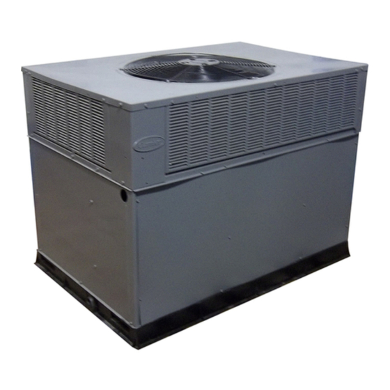
Fig. 1-Unit 48GP
RULES FOR SAFE INSTALLATION AND OPERATION
Improper installation, adjustment, alteration, service, mainte-
nance, or use can cause carbon monoxide poisoning, fire, or
an explosion which can result in serious injury or unit
damage. Consult a qualified installer, service agency, or gas
supplier for information or assistance. The qualified installer
or agency must use only factory-authorized kits or accessories
when modifying this product.
Understand the signal words -DANGER, WARNING, and
CAUTION. DANGER identifies the most serious hazards which
will result in severe serious injury or death. WARNING indicates
a condition that could result in serious injury or death. CAUTION
is used to identify unsafe practices which would result in minor or
moderate injury or product and property damage.
The power supply (volts, phase, and hertz) must correspond to that
specified on unit rating plate.
The electrical supply provided by the utility must be sufficient to
handle load imposed by this unit.
This installation must conform with local building codes and with
NEC (National Electrical Code) and NFPA 70, NFPA 54/ANSI
Z223.1 latest revision, and NFGC (National Fuel Gas Code). Refer
to provincial and local plumbing or waste water codes and other
applicable local codes.
Approved for outdoor installation on wood flooring or on class A,
B or C roof covering materials.
Form 48GP-1SI
48GP, 48GPN
C99088
Pg 1
3-00
Replaces: New
Advertisement
Table of Contents

Related Manuals for Carrier 48GP Series


Summary of Contents for Carrier 48GP Series
-
Page 1: Table Of Contents
48GP, 48GPN Single Package Gas Heating/Electric Cooling Units With Puron® (R-410A) Refrigerant Visit www.carrier.com Installation, Start-Up, and Operating Instructions 48GP, 48GPN Sizes 024-060 NOTE: Read the entire instruction manual before starting the installation. Index Page SAFETY CONSIDERATIONS .............1 RULES FOR SAFE INSTALLATION AND OPERATION..1-2 RECEIVING AND INSTALLATION ..........2... -
Page 2: Receiving And Installation
Manufacturer is not responsible for any damage incurred in transit. 2" Check all items against shipping list. Immediately notify the nearest Carrier Air Conditioning office if any item is missing. EVAP. COIL COND. COIL C99014 To prevent loss or damage, leave all parts in original packages Fig. -
Page 3: Rig And Place Unit
46 3/16 17 3/8 TYP. 44 5/16 1 TYP. 13/16 SUPPORT B SUPPORT A (2) SIDE END VIEW DECK PAN (INSULATED) A99320 Fig. 4—Roof Curb Dimensions Top View SIDE PANEL 0.75" BASE PAN 4.0" BOTTOM SUPPLY 3.0" SUPPORT RIB(S) SEAL STRIP (FACTORY SUPPLIED) COUNTER FLASHING NAILER... - Page 4 REQ’D CLEARANCES FOR OPERATION AND SERVICING. in. (mm) REQ’D CLEARANCES TO COMBUSTIBLE MAT’L. in. (mm) Evaporator coil access side ....36 (914) Top of unit ......14 (355.6) Power entry side (except for NEC requirements) .
- Page 5 REQUIRED CLEARANCE FOR OPERATION AND SERVICING REQUIRED CLEARANCE TO COMBUSTIBLE MATL. in. [mm] in. [mm] EVAP. COIL ACCESS SIDE..............36.00 [914.0] TOP OF UNIT...................14.00 [355.6] POWER ENTRY SIDE..............36.00 [914.0] DUCT SIDE OF UNIT.................2.00 [50.8] (EXCEPT FOR NEC REQUIREMENTS) SIDE OPPOSITE DUCTS ..............14.00 [355.6] UNIT TOP ..................36.00 [914.0] BOTTOM OF UNIT ................0.50 [12.7] SIDE OPPOSITE DUCTS ..............36.00 [914.0]...
- Page 6 1. Application of the lifter to the load and adjustment of the lifts, 5. Attach safety straps directly to the field supplied rigging straps if any, that adapts it to various sizes or kinds of loads. or clevis clip. Do not attach the safety straps to the lifting brackets.
-
Page 7: Connect Condensate Drain
914-1371 (36”-54”) DUCTS 927.57 (36”-52”) SEAL STRIP MUST BE IN 1226.3 PLACE BEFORE PLACING (48.28”) UNIT ON ROOF CURB PLACE RIGGING STRAPS IN BASEPAN SLOT (BELOW HANDHOLDS) BEFORE RIGGING C99015 UNIT 48GP MAXIMUM WEIGHT Size 22.0 558.5 14.5 368.3 22.0 558.5 15.3 388.6... -
Page 8: Install Duct Connections
NOTE: The supply piping must be disconnected from the gas Install a gas supply line that runs to the heating section. Refer to Table 4 and the NFGC for gas pipe sizing. Do not use cast-iron valve during the testing of the piping systems when test pressure is pipe. - Page 9 Table 2—Physical Data — Unit 48GP — 024040-042090 UNIT SIZE 48GP 024040 024060 030040 030060 036060 036090 042060 042090 NOMINAL CAPACITY (ton) 2 1/2 2 1/2 3 1/2 3 1/2 OPERATING WEIGHT (lb) COMPRESSORS Scroll Quantity REFRIGERANT (R-410A) Quantity (lb) REFRIGERANT METERING DEVICE Orifice ID (in.) .057...
- Page 10 Table 4—Maximum Gas Flow Capacity* LENGTH OF PIPE, FT† NOMINAL IRON PIPE SIZE (IN.) INTERNAL DIAMETER (IN.) .622 — — .824 1.049 1 1/4 1.380 1400 1 1/2 1.610 2100 1460 1180 *Capacity of pipe in cu. ft. of gas per hr. for gas pressure of 0.5 psig or less. Pressure drop of 0.5-in. wg (based on a 0.60 specific gravity gas). Refer to Table C-4, National Fire Protection Association NFPA 54 †This length includes an ordinary number of fittings.
-
Page 11: Install Electrical Connections
Step 10—Install Electrical Connections The field-supplied disconnect switch box may be mounted on the unit over the high-voltage inlet hole when the standard power and low-voltage entry points are used. See Fig. 6 and 7 for acceptable location. The unit cabinet must have an uninterrupted, unbroken See unit wiring label and Fig. -
Page 12: Control Voltage Connections
Table 5—Electrical Data — 48GP VOLTAGE COMPRESSOR OUTDOOR FAN MOTOR INDOOR FAN MOTOR POWER SUPPLY UNIT RANGE V-PH-HZ SIZE 48GP MOCP* 208/230-1-60 13.5 61.0 19.7 208/230-1-60 14.7 73.0 21.3 208/230-3-60 63.0 14.9 208/230-1-60 15.4 83.0 23.7 208/230-3-60 12.2 77.0 19.7 460-3-60 35.0 208/230-1-60... -
Page 13: Heat Anticpator Setting
HEAT ANTICIPATOR SETTING — The room thermostat heat c. Inspect all field- and factory-wiring connections. Be sure anticipator must be properly adjusted to ensure proper heating that connections are completed and tight. performance. Set the heat anticipator, using an ammeter between d. - Page 14 Table 6—Heating Inputs GAS SUPPLY PRESSURE MANIFOLD PRESSURE HEATING NUMBER (IN. WG) (IN. WG) INPUT Natural Propane† (BTUH)* ORIFICES Natural Propane† 40,000 13.0 13.0 60,000 13.0 13.0 90,000 13.0 13.0 115,000 13.0 13.0 130,000 13.0 13.0 *When a unit is converted to propane, different size orifices must be used. See separate natural-to-propane conversion kit instructions. †Based on altitudes from sea level to 2000 ft.
- Page 15 3. Turn on gas to unit. 4. Remove cover screw over regulator adjustment screw on gas valve. 5. Adjust regulator adjustment screw to the correct manifold pressure, as specified in Table 6. Turn adjusting screw clockwise to increase manifold pressure, or turn adjusting screw counterclockwise to decrease manifold pressure.
- Page 16 Table 7—Air Delivery (Cfm) at Indicated Temperature Rise and Rated Heating Input HEATING TEMPERATURE RISE °F INPUT (BTUH) INPUT 40,000 1500 1200 1000 — — — — 60,000 2250 1800 1500 1286 1125 1000 — 90,000 — 2700 2250 1929 1688 1500 1350...
- Page 20 Airflow can be changed by changing the lead connections of the REFRIGERANT CHARGE — The amount of refrigerant charge blower motor. is listed on the unit nameplate. Refer to Carrier Refrigeration All 48GP units are factory wired for low speed and may need to be Service Techniques Manual, Refrigerants section.
Need help?
Do you have a question about the 48GP Series and is the answer not in the manual?
Questions and answers