
Related Manuals for Ultraflex UC 68-OBS


Summary of Contents for Ultraflex UC 68-OBS
- Page 1 Installation and Maintenance Manual HYDRAULIC CYLINDERS FOR SIDE MOUNT APPLICATIONS UC 68-OBS UC 132-OBS UC 133-IOB PARTNER (Dr. No. 23068/e 16/07/2019)
- Page 2 All ULTRAFLEX SpA products are designed and manufactured to ensure the best performance. To ensure your safety and to maintain a high quality level, ULTRAFLEX SpA products are guaranteed only if they are used with original spare parts (see attached document "Application Spare Parts").
-
Page 3: Table Of Contents
Installation and Maintenance Manual TABLE OF CONTENTS MANUAL USE AND SYMBOLS USED........................4 INTRODUCTION..........................5 W A R R A N T Y ................... . . 5 SECTION 1 - PRODUCT DESCRIPTION HYDRAULIC STEERING SYSTEM OPERATION..................6 WARNINGS FOR THE CORRECT PRODUCT USE ..................6... -
Page 4: Manual Use And Symbols Used
Installation and Maintenance Manual MANUAL USE AND SYMBOLS USED THE INSTALLATION AND MAINTENANCE MANUAL is the document accompanying the product from its sale to its replacement and discharge. The manual is an important part of the product itself. It is necessary to read carefully the manual, before ANY ACTIVITY involving the product, handling and unloading included. -
Page 5: Introduction
1. Two Year Limited Warranty. UFLEX USA, Inc. warrants that all products manufactured by UFLEX USA, Inc. or ULTRAFLEX S.p.A. and sold by UFLEX USA to the retail purchaser ("Purchaser") that for two (2) years after the date of manufacture to be free from defects due to material or workmanship, subject to the exclusions below. - Page 6 4. Transferability of Warranty. This limited warranty may not be transferred to subsequent purchasers. 5. Miscellaneous. UFLEX USA, Inc. is an affiliate of ULTRAFLEX S.p.A. UFLEX, USA, Inc., reserves the right to make changes in the design and construction of its products at any time, without notice and without any obligation to incorporate such changes into products of prior manufacture.
-
Page 7: Section 1 - Product Description
WARNING The UC 68-OBS, UC 132-OBS and UC 133-IOB side mount cylinders must not be installed on race boats. WARNING Dual engine applications require two steering cylinders and tie bar, when the combined engine horsepower exceeds 450hp, and/or when the boat speed exceeds 55 m.p.h. -
Page 8: Configurations
Installation and Maintenance Manual 1.3 Configurations The hydraulic cylinders for side mount installations UC 68-OBS, UC 132-OBS, UC 133-IOB model can be installed with different configurations according to the number and the type of engines used with a single or dual engine steering system. -
Page 9: Cylinder Description
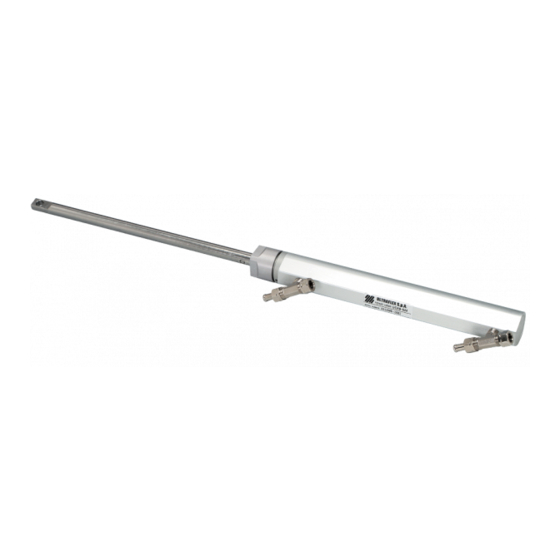
Installation and Maintenance Manual 1.4 Cylinder description UC 68-OBS, UC 132-OBS and UC133-IOB are hydraulic side mount cylinders which have been designed and manufactured to be used as a component in the hydraulic steering systems, as described in the previous paragraph. -
Page 10: Section 2 - Transport
Before using the equipment check that the product has not been damaged during transport. Also make sure that all the standard components are in the packaging (see list). In case of damage, notify the claim to the forwarder and inform the supplier. UC 68-OBS UC 132-OBS UC 133-IOB CONTENTS OF THE STANDARD PACKAGING: A ) No.1 cylinder body:... -
Page 11: Section 3 - Installation
3.1 Dimensions The following pictures show the dimensions of the various models. Before the installation consider the dimensions in order to avoid damages to the cylinder and to the boat. UC 68-OBS 329,3 mm - 12.96" 340 mm - 13.3"... -
Page 12: Cylinder Installation
Installation and Maintenance Manual 3.3 Cylinder installation Carry Insert the cylinder rod (2) in the extention (1) standard installation by locking it by means of the pin (3), then holding on the right side of the pin with your hand continue to insert the tilt the engine (see notice tube rod into the tilt tube. -
Page 13: Hose Installation
The hydraulic cylinders UC 68-OBS, UC 132-OBS and UC 133-IOB for side mount applications can be installed with different configurations according to the number and the type of engines used with a single or dual steering system. - Page 14 6. tie bar 3. bleed valves 3. cylinder 7. kit OB-2C 4. "T" fittings For: UC 68-OBS, UC 132-OBS, UC 133-IOB For: UC 68-OBS, UC 132-OBS, UC 133-IOB DUAL STATION / DUAL CYLINDER: DUAL STATION / SINGLE CYLINDER: 1. upper station helm 2.
-
Page 15: Filling And Purging
Installation and Maintenance Manual 3.6 Filling and purging After the first installation and after maintenance operations it is necessary to fill the system with hydraulic oil. This operation must avoid the air in the system, to ensure the good system operation. The hydraulic system must be filled from the highest point of the system, which means from the upper steering station. -
Page 16: Single Steering Station/ Single Cylinder
Installation and Maintenance Manual 3.6.2 Single steering station/ single cylinder - Unscrew the two bleed valves and manually push the rod up to the end stroke as shown in picture 1. - Position the oil bottle as explained in paragraph 3.6.1. - Close the bleed valve on the cylinder end stroke side and put a purged oil tank near the other bleed valve (as shown in picture 2). -
Page 17: Single Steering Station/Dual Cylinder
Installation and Maintenance Manual 3.6.3 Single steering station/ dual cylinder - Manually unscrew the two bleed valves on the cylinder "T" fittings and push the bleed cylinders to one side up to the end stroke. valves - Position the oil bottle as described in paragraph 3.6.1. -
Page 18: Dual Steering Station/Dual Cylinder
Installation and Maintenance Manual 3.6.5 Dual steering station/dual cylinder - Manually unscrew the two bleed valves bleed silver vent on the cylinder "T" fittings and push the valves cylinders to one side up to the end stroke. plug - Position the oil bottle near the main steering station (upper) according to what is described in paragraph 3.6.1. -
Page 19: Section 4 - Safety Warnings
Installation and Maintenance Manual 4 SAFETY WARNINGS This section shows the safety rules which must be followed for the correct equipment operation. We recommend reading carefully this section and also the other manuals supplied with the steering system components. 4.1 Safety warnings during use and installation RESPECT STRICTLY the following safety rules: UFLEX declines all responsibility in case the user does not follow these rules and it is not responsible for negligence during the use of the system. -
Page 20: Section 5 - Maintenance
Installation and Maintenance Manual 5 MAINTENANCE 5.1 Ordinary maintenance WARNING Poor installation and maintenance may result in loss of steering and cause property damage and/or perso- nal injury. Maintenance requirements change according to climate, frequency and the use. Inspections are necessary at least every year and must be carried out by specialized marine mechanics. - Page 21 Installation and Maintenance Manual The steering system is • Wrong oil has been used. • Drain the filling and bleeding system. stiff and hard to turn, even when the boat is not moving. WARNING UFLEX is not responsible for damage caused fluids that...
-
Page 22: Section 6 - Dismalting
Installation and Maintenance Manual 6 DISMALTING 6.1 Dismalting When for any reason, the steering system is put out of service, it is necessary to follow some rules in order to respect the environment. Sheaths, pipelines, plastic or non-metallic components must be disassembled and disposed of separately. The steering system CONTAINS POLLUTING OILS which must be disposed of according to the rules in force in the country. - Page 23 Installation and Maintenance Manual NOTE page 23 of 23 HYDRAULIC CYLINDER FOR SIDE MOUNT APPLICATIONS...
- Page 24 UFLEX USA Sarasota, FL 34243 - 6442 Parkland Drive...
Need help?
Do you have a question about the UC 68-OBS and is the answer not in the manual?
Questions and answers