
Related Manuals for Ultraflex UC 128-TS


Summary of Contents for Ultraflex UC 128-TS
- Page 1 Installation and Maintenance Manual HYDRAULIC CYLINDER FOR OUTBOARD ENGINES UC 128-TS PARTNER (REV. 1) (Dr. No. 22635/p 27/07/2018)
- Page 2 All ULTRAFLEX SpA products are designed and manufactured to ensure the best performance. To ensure your safety and to maintain a high quality level, ULTRAFLEX SpA products are guaranteed only if they are used with original spare parts (see attached document "Application Spare Parts").
-
Page 3: Table Of Contents
Installation and Maintenance Manual TABLE OF CONTENTS DOCUMENT REVISIONS...........................4 MANUAL USE AND SYMBOLS USED........................5 INTRODUCTION..........................6 WARRANTY..........................6 SECTION 1 - PRODUCT DESCRIPTION HYDRAULIC STEERING SYSTEM OPERATION.................8 WARNINGS FOR THE CORRECT PRODUCT USE ..............8 CONFIGURATIONS.........................9 UC128-TS CYLINDER DESCRIPTION......................10 TECHNICAL FEATURES..........................10 SECTION 2 - TRANSPORT GENERAL WARNINGS..........................11 PACKAGING CONTENTS........................11 SECTION 3 - INSTALLATION... -
Page 4: Document Revisions
Installation and Maintenance Manual DOCUMENT REVISIONS Rev. Date Revision description 20/02/2006 First edition 27/07/2018 New version with removable heads page 4 of 26 - HYDRAULIC CYLINDER FOR OUTBOARD ENGINE... -
Page 5: Manual Use And Symbols Used
Installation and Maintenance Manual MANUAL USE AND SYMBOLS USED THE INSTALLATION AND MAINTENANCE MANUAL is the document accompanying the product from its sale to its replacement and discharge. The manual is an important part of the product itself. It is necessary to read carefully the manual, before ANY ACTIVITY involving the product, handling and unloading included. -
Page 6: Introduction
Installation and Maintenance Manual INTRODUCTION This installation and maintenance manual represents an important part of the product and must be available to the people in charge of its use and maintenance. The user must know the content of this manual. UFLEX declines all responsibility for possible mistakes in this manual due to printing errors. - Page 7 Installation and Maintenance Manual 3. Limitations. THE REPAIR OR REPLACEMENT OF DEFECTIVE PARTS SHALL BE PURCHASER'S SOLE AND EXCLUSIVE REMEDY AND UFLEX USA, INC,'S SOLE AND EXCLUSIVE LIABILITY UNDER THIS WARRANTY. LABOR FOR REPLACEMENT IS NOT INCLUDED. UFLEX USA, Inc.'s obligation under this warranty is limited to the repair or replacement (at UFLEX USA, Inc.'s sole election) of any covered item found to be defective, when delivered by Purchaser pursuant to written authorization and instructions from UFLEX USA, Inc., shipping prepaid to UFLEX USA, Inc.'s plant or other designated repair facility.
-
Page 8: Section 1 - Product Description
All UFLEX steering systems must not be installed on boats equipped with engines whose maximum horsepower is higher than the horsepower rating approved by boat manufacturer. WARNING ULTRAFLEX hydraulic steering systems should not be used in racing applications. DANGER To avoid product damage, do not disassemble pre-assembled components. -
Page 9: Configurations
Installation and Maintenance Manual 1.3 Configurations The hydraulic cylinder for outboard engine UC128-TS model can be installed with different configurations according to the number and the type of engines used with a single or dual engine steering system. The possible configurations are: STEERING STATION ENGINE NUMBER NUMBER... -
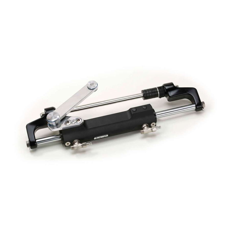
Page 10: Uc128-Ts Cylinder Description
450 Kg - 992 lbs (@70 bar) Inside diameter 35 mm - 1.37" Stroke 198 mm - 7.79" OL150 Ultraflex 544 mm (21.43") STANDARD VERSION (STARBOARD) PORT VERSION CAUTION *The cylinder output force is a theoretical force with a system pressure of 105 bar. This force does not correspond to the one normally used by the system but it represents the limiting conditions of use. -
Page 11: Section 2 - Transport
Installation and Maintenance Manual 2 TRANSPORT 2.1 General warnings The product weight with its packaging is 8kg (18 pounds) and so it can be handled manually. WARNING The staff in charge of handling must operate with protective gloves and safety shoes. 2.2 Packaging contents Before using the equipment check that the product has not been damaged during transport. -
Page 12: Section 3 - Installation
Installation and Maintenance Manual 3 INSTALLATION 3.1 Minimum transom requirements The following picture shows the minimum splash well dimensions. These dimensions must be respected in order to prevent the cylinder from being damaged when the outboard engine is completely tilted upwards. The picture shows also the minimum transom dimensions, needed for the installation and the correct operation of the engine steering cylinder. -
Page 13: Standard (Starboard)Cylinder Installation
Installation and Maintenance Manual 3.3 Standard (starboard) cylinder installation After removing the protective caps of the CAUTION fittings, manually center the rod (1) on the cylinder During the installation phases use only stainless body (2). steel tools to avoid the corrosion of the metal parts. In case of single cylinder installation mount the supplied caps on the cylinder body as shown in the picture. - Page 14 Installation and Maintenance Manual Fit the set screw (10) on the adjustment collar 10 With reference to the' "Application Guide" (11) and screw it to the right side of the tilt tube choose the spacers for the tilt tube rod. until it comes into contact with the tilt tube stop nut, even in case of port applications.
- Page 15 Installation and Maintenance Manual 17 Position the lock washers (15) and lock screw 16 Insert the washers (13) on the two ends of the (16) by using a 19mm wrench with a torque of 70[Nm] tilt tube rod, grease the nut thread (14) with (52 [lb·...
-
Page 16: Hose Installation
Installation and Maintenance Manual 3.4 Hose installation The two fittings mounted on the cylinder body are already oriented and are ready to be used. If for practical reasons the orientation must be changed, do as follows: 1. loose the locknut (A) by using a 11/16"wrench; 2. -
Page 17: Type Of Installation
Installation and Maintenance Manual 3.5 Type of installation The UC128-TS hydraulic cylinder for outboard engines can be installed with different configurations according to the number and the type of engines used with a single or dual steering system. The possible configurations are: CAUTION Connect hoses as shown in the following pictures:... -
Page 18: Filling And Purging
- Mobil DTE 11M NOTICE ULTRAFLEX will not be able to ensure the compatibility of the above mentioned oils with OL150 if the oil manufacturers vary their formulation; in particular, it will not be able to ensure its compliance with standard ISO 10592 concerning hydraulic steering systems. -
Page 19: Positioning Of The Oil Bottle
Installation and Maintenance Manual 3.6.1 Positioning of the oil bottle To carry out this operation, it is necessary to use the oil filling kit (1 needle, 1 transparent oil bottle pipe, 1 pipe connection and 1 spout for the oil bottle). This kit is NOT supplied. - Remove the pump cap and insert the fittings. -
Page 20: Single Steering Station/Dual Cylinder
Installation and Maintenance Manual - Open the other bleed valve and move purged oil tank to the other side. Holding the cylinder body in this position, turn the steering wheel as shown in picture 4, until oil without air bubbles comes out of the bleed valve. Then close the bleed valve. -
Page 21: Dual Steering Station/Dual Cylinder
Installation and Maintenance Manual WARNING For the additional steering station (lower) tank use only the silver non-vent plug (supplied with the "kit OB- 2S"). For the main steering station (upper) tank use only the black vent plug. - Repeat the procedure at least 3 times to ensure the absence of air in the system. NOTICE The purging procedure is the same for dual station, dual motor, single cylinder and tie bar. -
Page 22: Section 4 - Safety Warnings
Installation and Maintenance Manual 4 SAFETY WARNINGS This section shows the safety rules which must be followed for the correct equipment operation. We recommend reading carefully this section and also the other manuals supplied with the steering system components. 4.1 Safety warnings during use and installation RESPECT STRICTLY the following safety rules: UFLEX declines all responsibility in case the user does not follow these rules and it is not responsible for negligence during the use of the system. -
Page 23: Section 5 - Maintenance
WARNING If worn heads are not replaced, the cylinder cannot work properly, thus jeopardizing the safety of the user. ULTRAFLEX supplies a proper kit containing the components to be used for replacement. NOTICE The kit is supplied with the replacement instructions. -
Page 24: Troubleshooting
Installation and Maintenance Manual 5.3 Troubleshooting WARNING Whenever the following checks need the removal and/or disassembly of the steering system components, such work must be carried by specialized staff. UFLEX offers general information only and is not responsible for any consequences resulting from incorrect disassembly. PROBLEM CAUSE SOLUTION... - Page 25 Installation and Maintenance Manual The steering system is • The steering wheel is too • Replace the steering wheel with a bigger one. easy to turn at the dock but small. becomes hard to turn when the boat is in motion. WARNING Only within the maximum dimensions allowed by the helm.
-
Page 26: Section 6 - Dismantling
Installation and Maintenance Manual 6 DISMANTLING 6.1 Dismantling When for any reason, the steering system is put out of service, it is necessary to follow some rules in order to respect the environment. Sheaths, pipelines, plastic or non-metallic components must be disassembled and disposed of separately. The steering system CONTAINS POLLUTING OILS which must be disposed of according to the rules in force in the country. - Page 27 UFLEX USA Sarasota, FL 34243 - 6442 Parkland Drive...
- Page 29 Installation instructions HEAD REPLACEMENT KIT UC 128-TS CYLINDER PARTNER (Dr. No. 34540/b 06/05/2019)
- Page 30 All ULTRAFLEX SpA products are designed and manufactured to ensure the best performance. To ensure your safety and to maintain a high quality level, ULTRAFLEX SpA products are guaranteed only if they are used with original spare parts (see attached document "Application Spare Parts").
- Page 31 1. Two Year Limited Warranty. UFLEX USA, Inc. warrants that all products manufactured by UFLEX USA, Inc. or ULTRAFLEX S.p.A. and sold by UFLEX USA to the retail purchaser ("Purchaser") that for two (2) years after the date of manufacture to be free from defects due to material or workmanship, subject to the exclusions below.
- Page 32 4. Transferability of Warranty. This limited warranty may not be transferred to subsequent purchasers. 5. Miscellaneous. UFLEX USA, Inc. is an affiliate of ULTRAFLEX S.p.A. UFLEX, USA, Inc., reserves the right to make changes in the design and construction of its products at any time, without notice and without any obligation to incorporate such changes into products of prior manufacture.
- Page 33 CAUTION This kit must be used with hydraulic cylinders for outboard engines UC 128-TS only. CAUTION During each disassembly phase, put the cylinder in a suitable position to prevent Loctite ® residues from falling into it. NECESSARY TOOLS Open end wrench 9/16”...
- Page 34 Open bleed valve “1” and put a tank to collect oil (refer to picture B on the following page). Turn the steering wheel slowly (as shown in the picture) so that the oil can come out through the hoses and the bleed valve. NOTE Hold the cylinder body with the hand to prevent movements.
- Page 35 CYLINDER REMOVAL CAUTION Before removing the cylinder from the engine, remove one or both bullhorns from the rod. In case of necessity, replace both heads. CAUTION During removal, any worn and unusable component must be replaced. Undamaged components or parts in good conditions can be reused. Remove hoses “2”...
- Page 36 By using a 3/4” wrench, remove nuts and their washers “7” on the two ends of the tilt tube rod. NOTE Eliminate the nuts and washers which will be replaced by those supplied with the kit. HEAD REPLACEMENT NOTE Heads must be replaced on a workbench provided with suitable vice. CAUTION Replace one head at a time to prevent the piston from coming out of its seat and subsequently from damaging its gasket irreparably.
- Page 37 When removing the safety screw, make sure that Loctite ® residues do not fall into the cylinder. CAUTION In order to remove the head and install the new one, only use kit Ultraflex code no. 43395W, which is NOT SUPPLIED WITH THE “HEAD REPLACEMENT KIT”.
- Page 38 Place the proper tool “13, taking care to insert the 4 pivots of the head into the front holes. By means of a 19 mm square wrench, unscrew the head to be replaced. Put the proper tool “14” on the rod to make the introduction of the gaskets located on the spare head easier.
- Page 39 20 Install the cylinder following the instructions provided in paragraph 3.3 of the UC 128-TS manual starting from point 2. 21 Carry out the system filling and draining procedure as described in pargraph 3.6 of the UC 128-TS manual. pag. 11...
- Page 40 UFLEX USA Sarasota, FL 34243 - 6442 Parkland Drive...
Need help?
Do you have a question about the UC 128-TS and is the answer not in the manual?
Questions and answers