
Related Manuals for Peter electronic BR Series

Summary of Contents for Peter electronic BR Series
- Page 1 e l e c t r o n i c Assembly and Commissioning Instructions Braking Devices BR 230/400 - 10...400 Quality is our Drive.
-
Page 2: Table Of Contents
BR 230/400-10...400 as per 04/10 11600.10001 Table of Contents Page Safety notes Conformity General description Usage to the intended purpose EC Declaration of Conformity Block diagram Functional description (see connection diagram) LED indicators Control inputs and outputs Control inputs Control outputs Potentiometers 10. - Page 3 BR 230/400-10...400 These commissioning instructions were prepared with great care. Nevertheless, PETER electronic GmbH & Co. KG does not assume liability for damage resulting from mistakes possibly contained in this manual. Technical changes that serve to improve the product are subject to change without notice.
-
Page 4: Safety Notes
BR 230/400-10...400 Safety notes The described devices are electrical equipment for use in industrial electrical power installations. An impermissible removal of the covers during operation can cause serious damage to your health, since these devices contain live parts with high voltages. -
Page 5: General Description
BR 230/400-10...400 General description The electronic braking devices of the BR...-type enable a non-wearing braking of three-phase asynchronous motors and A.C. motors. The braking devices are used for drives that due to safety or functional reasons have to be reliably slowed down. Special features •... -
Page 6: Ec Declaration Of Conformity
The manufacturer / company placing the product on the market (authorized representatives of the manufacturer / companies placing the product on the market that are established within the Community) Name / Address: Peter Electronic GmbH & Co.KG Bruckäcker 9 92348 Berg Germany... -
Page 7: Block Diagram
BR 230/400-10...400 Block diagram L2/N Pulse Timing stage control Starting logic Braking contactor Interlock control Devices from 40A on braking contactor external braking signal main contactor interlock... -
Page 8: Functional Description (See Connection Diagram)
BR 230/400-10...400 Functional description (see connection diagram) After switching on the operating voltage on L1 and L2 the main contactor interlock (terminal X5,X6) closes. The motor can be started. A starting logic makes sure that braking is not yet initiated when the plant is switched on with the master switch while the motor is still switched off. -
Page 9: Control Inputs And Outputs
BR 230/400-10...400 Control inputs and outputs Control inputs Control Designation Description terminals X3, X4 Starting contact Connection of a break contact of the motor contactor Caution: Danger to life through electric shock! The terminals X3, X4 carry mains potential. If a switch or contactor contact is connected to these terminals, it must have a test voltage of 2.5kV. -
Page 10: Potentiometers
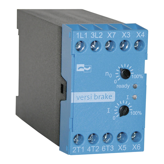
BR 230/400-10...400 Potentiometers With the potentiometers on the front panel of the BR-devices the following paramteters can be adjusted. „I“ Adjusting the braking current Adjust the braking current as small as possible, in order to avoid unnecessary heating ot the power semiconductors and the motor. This is especially important in the case of frequent operation. -
Page 11: Technical Data
BR 230/400-10...400 10. Technical data Type designation 230-10 230-20 230-40 230-60 230-100 230-200 230-400 BR ..400-10 400-20 400-40 400-60 400-100 400-200 400-400 BR230 ... 220/240V ±10% 50/60Hz other voltages Nominal voltage BR400 ... 380/415V ±10% 50/60Hz upon request according to DIN EN 50160 (IEC 38) Power draw of the 6 VA... -
Page 12: Commissioning
BR 230/400-10...400 Commissioning The device is to be put into operation in 3 steps:: 1. Mounting 2. Connection and 3. Parameter setting 11.1 Mounting instructions Caution: Danger to life through electric shock! The following conditions are to be complied with in order to ensure a safe and reliable operation of the BR ...: 1. -
Page 13: Commissioning
BR 230/400-10...400 3. When using braking devices with separate braking contactors (devices with rated currents from 40A up), braking contactor and motor contactor have to be interlocked against each other. (Electrical interlock with break contact) 11.3 Commissioning Sequence of commissioning: 1. -
Page 14: Dimensioning Rules
BR 230/400-10...400 Adjusting the braking time The time, in which the braking current flows, is to be adjusted with the potentiometer "t". It should be so long that, as soon as the motor has come to rest, the braking current is switched off. When the motor has reached operating temperature, check the settings and, if necessary, readjust them. - Page 15 On the basis of the recommended I²t-value, braking current, and possibly the c.d.f., the fuse supplier is able to select a suitable type. Due to the great variety of producers, sizes and types, PETER electronic does not recommend any particular fuses.
-
Page 16: Permissible Braking Frequency Of Br
BR 230/400-10...400 12.3 Permissible braking frequency of BR ...-10 and BR...-20 The braking frequency depends on the adjusted braking current. The braking devices of the BR 230/400-10-20A type allow the following braking frequencies: Braking current Braking time Braking frequency rated device current 1 braking per 25s 1 braking per 70s 75% rated device current... - Page 17 BR 230/400-10...400 table 3 Reduction of the permissible max. braking current in the case of braking times exceeding 40 seconds for braking devices of the BR type up to 40A 100,0 90,0 80,0 70,0 60,0 50,0 40,0 30,0 20,0 10,0 80 100 120 140 160 180 200 220 240 260 280 300 320 340 360 380 400 Braking time in seconds...
-
Page 18: Dimensions
BR 230/400-10...400 13. Dimensions BR 230-10 ... 20 BR 400-10 ... 20 BR 230-40 ... 400 BR 400-40 ... 400 for M4 Depth: 172mm 146 (286 with BR 230/400-400) 175 (315 with BR 230/400-400) All dimensions in mm! -
Page 19: Typical Connections
BR 230/400-10...400 14. Typical connections 14.1 Connection diagramm Attention: If, in spite of a long braking time, the braking current is instantly switched off, BR 230-10 ... 20 the braking current is adjusted to a too high value. BR 400-10 ... 20 Typ BR 230 L2/N moving-iron... - Page 20 BR 230/400-10...400...
- Page 21 BR 230/400-10...400...
Need help?
Do you have a question about the BR Series and is the answer not in the manual?
Questions and answers