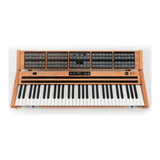
NONLINEAR LABS C15 Tutorial
Sound generation
Hide thumbs
Also See for C15:
- User manual (201 pages) ,
- Manual (24 pages) ,
- Quick start manual (24 pages)
Table of Contents
Advertisement
Quick Links
Advertisement
Table of Contents

Related Manuals for NONLINEAR LABS C15


Summary of Contents for NONLINEAR LABS C15
- Page 1 Sound Generation Tutorial...
- Page 3 NONLINEAR LABS GmbH Helmholtzstraße 2-9 E 10587 Berlin Germany www.nonlinear-labs.de info@nonlinear-labs.de Author: Matthias Fuchs Document Version: 1.6 Date: August 09, 2018 © NONLINEAR LABS GmbH, 2018, All rights reserved.
-
Page 5: Table Of Contents
Contents About these tutorials ....6 Init Sound ..... . Oscillator Section / Creating Waveforms . -
Page 6: About These Tutorials
C15 synthesis engine, and to learn about all the details of any of the parameters of the instrument. A tutorial will teach you basic aspects of the C15’s concepts as well as the various components of the sound engine, and how they interact with each other, in a hands-on manner. - Page 7 Data values are bold and in square brackets: [ 60.0 % ] Controllers, as the Ribbons and Pedals, are labelled in Bold Capitals: PEDAL 1 Programming steps to be performed are indented to the right and marked with a triangle, like this: ▶...
- Page 8 Basic Conventions Before starting, it is crucial to understand some basic conventions of the front panel – more on this in the Quickstart Guide: • When a button on a Selection Panel is pressed, the parameter is selected and its value can be edited.
- Page 9 Edit Panel Setup Button Panel Unit Display Setup Preset Setup Button Sound Button Soft Buttons 1 to 4 Sound Store Store Button Info Button Fine Button Encoder 10 Enter Button 11 Edit Button Info Fine Enter Edit 12 Shift Button 13 Default Button 14 Dec / Inc Buttons Default...
-
Page 10: Init Sound
Comb Filter. The tutorial will be topped off by an insight into the feedback capabilities (which is another very interesting way of creating sounds). As you certainly know already, the C15’s oscillators initially generate sine-waves. The real fun starts when these sine-waves are warped to generate complex wave- forms with amazing sonic results. - Page 11 ߃ Excursion – A Short Glimpse at the Signal Path Before we proceed further, let’s have a brief look at the C15’s structure / signal path: Feedback Mixer Shaper Oscillator A Shaper A FB Mix Envelope A State Comb Variable...
-
Page 12: Oscillator Section / Creating Waveforms
Oscillator Section / Creating Waveforms A typical parameter screen of the Panel Unit display looks like this: 1 Group Header 3 Graphical Indicator 5 Soft Button Labels 2 Parameter Name 4 Parameter Value 6 Main and Sub Parameters Oscillator Basics Let’s (de)tune Oscillator A: Press Pitch (Oscillator A) ▶... -
Page 13: Oscillator Self-Modulation
Turn the Encoder to [ 0.00 % ]. Each key is playing at the same pitch now. ▶ ߊ A key tracking close to 0.00% can be very useful when an oscillator is used as LFO-like modulation source or slow PM-carrier. More on this later…... -
Page 14: Introducing The Shaper
Let’s make Oscillator self-modulation dynamic and control Self-PM of Oscillator A by Envelope A: Set the Encoder to approx. [ 70,0 % ] self modulation amount. ▶ Press PM Self (Oscillator A) again. Watch the Display: Env A is highlighted ▶... - Page 15 Then set the Drive to [ 20.0 dB ]. ▶ Press Fold (Shaper A). ▶ Turn the Encoder slowly and play some notes. ▶ Press Asym (Shaper A). ▶ Turn the Encoder slowly and play some notes. ▶ ߊ Fold, Drive and Asym(metry) warp the signal to generate various wavesh- apes with very different harmonic content and timbral results.
-
Page 16: Both Oscillators Together
Excursion – the C15’s signal routing / blending As with all signal routings in the C15, the Shaper is not switched in or out of the sig- nal path but continuously blended with another (usually the dry) signal. This makes sense since it provides great morphing capabilities without any steps or clicks in the sound. - Page 17 Turn the Encoder to approx. [ 60.0 % ]. ▶ ߊ Now, both oscillators are sending their signals through the Output Mixer. Press Level (Output Mixer). ▶ Turn the Encoder to approx. [ -10.0 dB ]. ▶ ߊ You have just reduced the mixer’s output signal enough to avoid unwanted distortion.
- Page 18 Detuning Oscillator B: Press PM Self (Oscillator A). ▶ Turn the Encoder to [ 60.00 % ]. ▶ ߊ We simply wanted to make the entire sound somewhat brighter, to improve the audibility of the following example. Press Pitch (Oscillator B). ▶...
- Page 19 A second crucial parameter is the intensity of the phase modulation or “modulation index”. In the C15, the appropriate parameters are called “PM A” and “PM B”. Different values will produce radically different timbral results. The interaction between the pitch of the respective oscillators and their modulation depth settings (“PM A / B”) is...
- Page 20 Controlling the Modulator by an Envelope: As you have learned in the meantime, frequency and mod depth of the modulator (here Oscillator B) are crucial for shaping sound using PM. Unlike classic subtractive synthesis, it is very easy to generate a wide range of noisy and “metallic” timbres that offer lots of potential when emulating acoustic instruments, like e.g.
- Page 21 Using Key Tracking as a sound parameter: Press Pitch (Oscillator B) until Key Trk is highlighted in the display. ▶ Turn the Encoder and dial in [ 50.00 % ] while playing some notes. ▶ ߊ The Key Tracking of Oscillator B has been enabled again which forces Oscillator B to change its pitch depending on the note played.
- Page 22 You certainly want to explore a lot of expressive potential when enjoying your sounds. The C15 provides a lot of capabilities to do so (Ribbon Controllers, Pedals etc). For starters, we would like to introduce Keyboard Velocity. Its default setting is 30.0 dB which works pretty well in many cases.
- Page 23 Please note that, in contrast to most other (analog) synthesizers with a dedicated LFO, the C15 sports an oscillator/LFO per voice. They are not phase-synced which helps to animate many sounds in a natural way.
-
Page 24: The State Variable Filter
The State Variable Filter To introduce the State Variable Filter (S.V. Filter), we should first set up the oscillator section to produce a sawtooth waveform which is rich in overtones. This is a good input signal fodder to explore the State Variable Filter. First, please load the Init sound –... - Page 25 ߊ The parameter currently selected (Cutoff) is now controlled by RIBBON 1, or your finger tip ྇ When using the C15’s Macro Controls, the Ribbons / Pedals can control various parameters at the same time. This very interesting topic will be covered in a later tutorial. Stay tuned.
- Page 26 ߃ Excursion: The S.V. Filter functionality The S.V. Filter is a combination of two resonating two-pole state-variable filters, each with a slope of 12 dB. Cutoff and Resonance can be controlled manually or modu- lated by Envelope C and Key Tracking. L–B–H Cuto Spread...
- Page 27 • B – the first filter section works as a highpass, the second as a lowpass. Low and high frequencies are both attenuated and a frequency band with variable width (“Spread”) passes the S.V. Filter. Particularly at higher Resonance settings, vowel/ vocal-like sounds can be achieved.
-
Page 28: The Output Mixer
Press Spread (State Variable Filter) again until L–B–H is highlighted in the ▶ display. Sweep the Encoder across the entire value range and dial in the default ▶ value [ 0.0 % ] (Lowpass). ߊ Using the L–B–H parameter, you can morph continuously from lowpass through bandpass to highpass. - Page 29 Using the Output Mixer: Press S.V. Filter (Output Mixer). ▶ Set the Encoder to approx. [ 50.0 % ]. ▶ Press A (Output Mixer). ▶ Set the Encoder to approx. [ 50.0 % ]. ▶ ߊ You have just combined the output signal of the S.V. Filter with the direct (unfiltered) signal of Oscillator A.
-
Page 30: The Comb Filter
The Comb Filter can also work as a resonator and it can produce periodic waveforms like an oscillator this way. It is an integral part of the C15’s sound gen- eration, and it can be useful when achieving imbral characteristics of e.g. plucked or bowed strings, blown reeds, horns, and many strange things in between and far beyond that. -
Page 31: The Very Basic Parameters
Enabling the Comb Filter: To explore the Comb Filter, dial in a simple sawtooth-wave sound – we have absolutely no reason to believe you don’t already know how to do this. Okay, here comes a brief reminder for your convenience: Load the Init sound and set the Output Mixer level A to [ 50.0 % ]. - Page 32 Non-inverted Mix Inverted Mix Magnitude Magnitude (dB) (dB) Frequency Frequency Ratio Ratio 20 dB 20 dB 0 dB 0 dB – 20 dB – 20 dB – 40 dB – 40 dB – 60 dB – 60 dB – 80 dB –...
-
Page 33: More Advanced Parameters / Refining The Sound
߃ Excursion – Some Nuts and Bolts of Physical Modelling What you have just programmed into your C15 is a very simple example of a sound-generation type usually referred to as “Physical Modelling”. It comprises a dedicated signal source – the exciter – and a resonator, in our case the Comb Filter. - Page 34 Hi Cut: Press Hi Cut (Comb Filter). ▶ Sweep the Encoder across the entire range and play notes. Then dial in a ▶ value of [ 110.00 st ]. ߊ The signal path of the Comb Filter features a lowpass filter that atten- uates high frequencies.
-
Page 35: Varying The Exciter Settings (Oscillator A)
the lowest octave of a piano, which sounds quite metallic. This is because the physical qualities of those heavy-gauge piano strings, found in the lowest octave, are quite similar to those of metal tines or plates. Press AP Tune (Comb Filter) until AP Reson is highlighted in the display. ▶... - Page 36 Using “Fluctuation”: Press Fluct (Oscillator A). ▶ Sweep the Encoder slowly across the entire range while playing some notes. ▶ Then dial in approx. [ 60.0 % ]. ߊ At various pitch ratios between Oscillator A (exciter) and Comb Filter (resonator), the frequency boosts and attenuations are very strong and limited to narrow frequency bands.
-
Page 37: Using Feedback Paths
Using Feedback Paths As you already know (at least we are confident you do), the C15’s signal path provides various ways of feeding back signals which means that certain amounts of signals can be tapped at a specific point in the signal flow and reinserted at an earlier stage. - Page 38 Another way to continuously excite the resonator is feeding a certain amount of its output signal back to its input. On the C15, this can be done by using the Feedback Mixer, which will be introduced right now: Press Comb (Feedback Mixer).
- Page 39 Shaping the feedback sound: … by using negative feedback level settings: Press Comb (Feedback Mixer). ▶ Turn the Encoder to [ –40.0 % ]. ▶ ߊ At negative settings, the feedback signal is inverted. This will typically have a “damping” effect and shortens the sound produced. If you are operating the Comb Filter at negative Decay values, the negative values in the Feedback Mixer will drive it into self-oscillation.
- Page 40 Try different Sustain levels while playing notes and dial in approx. [ 5 % ]. ▶ Press Fluct (Oscillator A). ▶ Try different Fluctuation levels while playing notes. ▶ ߊ By changing the envelope, pitch, and signal spectrum of Oscillator A, the self-oscillating Comb-Filter will generate a plethora of different timbres.
- Page 41 Oscillator A excites the Comb Filter and is not audible as such either. … by using the effects output as feedback signal: Another interesting way to shape comb filter / physical modeling sounds of the C15 is using the feedback path of the effects section.
- Page 42 Recap: The Feedback Paths • Together with the Oscillator / Shaper sections and the Comb Filter, the feedback paths of the C15 provide interesting physical modelling capabilities. • Using feedback paths produces sustained tones without using sustaining oscilla- tor (exciter) settings – great for sounds with woodwind, brass, and bowed-strings- like character.
Need help?
Do you have a question about the C15 and is the answer not in the manual?
Questions and answers