Advertisement
Quick Links
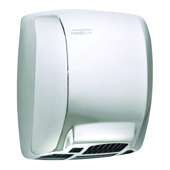
Mediflow Logyc Dry hand dryer
Safety regulations
All installation, maintenance and repair tasks must be carried out by qualified
technicians.
Mediclinics remembers the importance of:
1. Becoming familiar with the equipment and carefully reading the user manual prior to
operating.
2. Disconnecting power prior to beginning any repair or maintenance action.
3. Exercising care in accordance with the procedures included herein.
General maintenance
Preventive Maintenance - Cleaning
depending on the dryer's operating cycles.
Inspect the units
annually or quarterly,
Clean the active parts of the unit, such as: the motor, the heating element, the fan and
the electronic circuit board with a soft brush.
Maintain the air inlet and outlet free of dust and other obstructions; use a soft flat ended
brush.
Removal of the casing
Consult the safety regulations prior to carrying out any work on the unit.
Release the screws that attach the casing (2 units) using the supplied tamper-
proof screwdriver.
Advertisement

Related Manuals for Mediclinics Mediflow Logyc Dry


Summary of Contents for Mediclinics Mediflow Logyc Dry
- Page 1 Mediflow Logyc Dry hand dryer Safety regulations All installation, maintenance and repair tasks must be carried out by qualified technicians. Mediclinics remembers the importance of: 1. Becoming familiar with the equipment and carefully reading the user manual prior to operating.
- Page 2 The casing is fixed to the base by means of inner bolts. Extract the lower part of the casing, as shown in the image, and lift it slightly to release the anchors. To avoid scratching the casing, place it on a flat surface with the visible part facing upward.
- Page 3 Motor Characteristics - Type: Universal brush motor - Power: 250 W - Speed of rotation: 5,500 rpm - Class F - Incorporates a safety thermal limiter Maintenance The corrective maintenance of the motor consists of replacing the brushes. The brushes have a theoretical useful life of 3,000 hours and must be replaced when their length is shorter than 5 mm.
- Page 4 Move the clip to one side to release the brush. Remove the brush from its location and replace it. Carry out the same procedure for the second motor brush. Assemble by following the previous steps in reverse order.
- Page 5 Replacement of the motor For greater safety, we recommend you disconnect the three heating element cables that go to the three-way terminal block of the electronic circuit board. Use pliers to carefully extract the two circlips that secure the heating element.
- Page 6 Rotate the heating element a quarter turn clockwise, until it is released from its anchors. Carefully remove the heating element from its position.
- Page 7 Disconnect the cables of the motor that go to the two-way terminal block located in the electronic circuit board. Carefully remove the electronic circuit board from the guide located at the base by bending the clips that are located in the volute.
- Page 8 Release the screw attaching the volute to the base. Remove the heating element ring located to the left of the fan.
- Page 9 Loosen the set screw that secures the fan to the drive shaft, inserting an Allen key through the hole in one of the fan blades. Remove the fan. Release the two lateral springs that fasten the motor...
-
Page 10: Heating Element
Remove the motor from its position and replace it. Fit it by following the previous steps in reverse order. Heating element Characteristics - Band type coiled cable double heating element in Cr, Al and Fe. - On MICA body. - Incorporates a thermal limiter. - Automatic disconnection 0.5 seconds before the motor stops. - Page 11 Replacement of the heating element Disconnect the three heating element cables that go to the three-way terminal block of the electronic circuit board. Use pliers to carefully extract the two circlips that secure the heating element.
- Page 12 Rotate the heating element a quarter turn clockwise, until it is released from its anchors. Remove the heating element from its housing in the volute and replace it. Fit it by following the previous steps in reverse order.
-
Page 13: Electronic Circuit Board
Electronic Circuit Board Characteristics - Electronic sensor, with infrared beam. - Detection distance from 5 to 20 cm adjustable by means of a potentiometer. - Polycarbonate viewer. - Selective detection of fixed targets. - Automatic disconnection system after 120 seconds of continued use. - Automatic temperature regulation at the air outlet according to the room temperature. - Page 14 Disconnect the cables of the motor that go to the two-way terminal block located in the electronic circuit board. Carefully remove the electronic circuit board from the guide in the base by bending the clips located in the volute.
- Page 15 Disconnect the electronic circuit board from the terminal block in the junction box of the base and replace it. Fit it by following the previous steps in reverse order. Insert the circuit board into the guide at an angle of 45º for it then to be positioned perpendicular to the base.
- Page 16 Release the LED cables from the guide that secures them to the volute. Remove the LEDs from their housing.
- Page 17 Setting the detection distance The detection distance can be set between 5 and 20 cm, by means of the potentiometer located in the chassis of the LED cables.
Need help?
Do you have a question about the Mediflow Logyc Dry and is the answer not in the manual?
Questions and answers