Table of Contents
Advertisement
Quick Links
Advertisement
Table of Contents

Related Manuals for AmeriWater MediQA MSP Series


Summary of Contents for AmeriWater MediQA MSP Series
- Page 1 AmeriWater Operation & Maintenance Manual The Water Purification Specialists MediQA Reverse Osmosis System MODELS MSP AND MDP 3345 Stop 8 Rd, Dayton, OH 45414 | 800 535 5585 | www.ameriwater.com 98-0157 Rev K Manufactured With Pride in The USA...
-
Page 2: Table Of Contents
TABLE OF CONTENTS CONTACT DETAILS ..................... 4 INTRODUCTION AND SAFETY INFORMATION ............... 5 INDICATIONS FOR USE ..................5 CONTROLS ......................5 ALARMS AND MAINTENANCE ................. 5 CAUTION AND WARNING STATEMENTS ..............6 GENERAL SAFETY INFORMATION ................7 STANDARD FEATURES ....................10 MEDIQA STANDARD FEATURES ................10 ELECTRICAL SPECIFICATIONS / CONNECTIONS .............10 3.2.1... - Page 3 5.4.2 Heatsan Water Loss Lockout ................24 5.4.3 Alarm Panel Connections ................25 5.4.4 Installation Kit Details ..................25 OPERATOR INTERFACE ....................33 OPERATIONS MENU .....................33 6.1.1 OPERATION MENU screen ................34 6.1.2 Operation Periods ..................36 MAIN MENU ......................37 6.2.1 VIEWER button .....................37 6.2.2 ACTIVITY DETAILS button ................38 6.2.3 ACTIVITY LOG button ..................39 6.2.4...
- Page 4 EXTERIOR SURFACE CLEANING ................61 CHEMICAL CLEANING ..................61 8.2.1 Method:......................62 APPROVED CHEMICALS ..................63 RO HEAT DISINFECTION PROCEDURE ..............63 8.4.1 Manual RO Heat Disinfection ................64 8.4.2 Automatic RO Heat Disinfection ..............64 MAINTENANCE ......................65 THERMOSTAT TESTING ..................65 FAULTY ITEMS ....................66 MEDICAL DEVICE TRACEABLE COMPONENTS ............67 REPLACEMENT PART HISTORY LOG SHEET............68 FLOW DIAGRAMS ....................69 WIRING SCHEMATIC ....................71...
-
Page 5: Contact Details
For all spares and consumables contact: Customer Service Tel No: 1-800-535-5585 For all service or technical support contact: Technical Support Tel No: 1-800-535-5585 Web address: www.ameriwater.com (Or your local authorized AmeriWater dealer) Useful Telephone Nos. Tel No………………………………Contact Name:………………………………. Tel No………………………………Contact Name:………………………………. 98-0157 Rev K... -
Page 6: Introduction And Safety Information
AAMI and Federal (U.S.) standards. The AmeriWater MediQA is intended for use in water rooms in a hospital, clinic, or dialysis center. The device includes an integrated heat sanitization process. -
Page 7: Caution And Warning Statements
AmeriWater reserves the right to make engineering refinements to the equipment that may not be described herein. Any questions that cannot be answered specifically by these instructions should be addressed to AmeriWater or their agents for a response. AmeriWater will not accept any responsibility for any equipment supplied or the... -
Page 8: General Safety Information
2.5 GENERAL SAFETY INFORMATION Explanation of symbols and references This symbol refers to any immediate dangers that may threaten the safety and life of persons. Danger Failure to observe these notices will have severe consequences on health and safety, including life-threatening injuries. This symbol refers to a possible danger that threatens the safety and life of persons. - Page 9 Operating staff Only persons who have read and understand these Operation Instructions should be permitted to operate the unit. When operating the unit, it is particularly important to observe the safety information strictly. Mechanical force Some parts of the system could be under pressure of up to 300 psi. Always make sure the pressure has dispersed from the unit before repairs and maintenance tasks are carried out.
- Page 10 To obtain warranty service, notice must be given to the manufacturer within 30 days of the discovery of the defect. There are no warranties on the AmeriWater system beyond those specifically described above. All implied warranties, including any implied warranty of merchantability or of fitness for a particular purpose are disclaimed to the extent they might extend beyond the above periods.
-
Page 11: Standard Features
3. STANDARD FEATURES 3.1 MEDIQA STANDARD FEATURES • Flow rate, temperature, pressure and water quality monitoring. • System status alarms. • Semi - automated chemical cleaning • Touch screen user interface. • Heat sanitization feature 3.2 ELECTRICAL SPECIFICATIONS / CONNECTIONS 3.2.1 Mains supply See specification. -
Page 12: Environmental
3.3 ENVIRONMENTAL Applicable to all product variants Parameter Value Room storage and operating temperature range. 41-104°F (5 to 40°C) Relative humidity. 30 to 80% Maximum altitude. 6562 ft Transport and storage temperature 41-104°F (5 to 40°C) (limited by RO membranes). The EMC environment must be within the limits to which the RO has been tested. -
Page 13: Specification Data
3.5 SPECIFICATION DATA Single Pass MediQA Dual Pass MediQA Catalog Number Performance Permeate flow rate 12.0 10.0 @ 77°F** Dimensions Height Inches Width Inches Depth Inches Weights Working 1310 1375 1660 2285 Shipping* 1050 1100 1370 1970 Services-Feed Water Pressure 30/80 psi Free Chlorine Following activated carbon, free chlorine level must be <... -
Page 14: Performance Parameters
3.6 PERFORMANCE PARAMETERS MediQA Performance Parameters Single Pass Dual Pass Catalog Number MSP2 MSP3 MDP2 MDP4 Flow Rates Product Flow Specification (GPM) Product Flow Range (GPM) 7.2-10.8 9.6-14.4 4.8-7.2 8-12 Nominal: 5 Nominal: 6.5 Nominal: 5 Nominal: 6.5 Stage 1 Concentrate Flow (GPM) 3.8-9 5-12 3.8-9... -
Page 15: Operational Overview
4. OPERATIONAL OVERVIEW The MediQA is available as a single pass or dual pass reverse osmosis (RO) unit to be used for purification of potable water for renal dialysis applications. Potable water enters the MediQA through an inlet solenoid valve filling the feed water tank. - Page 16 inadvertent supply of poor water quality to the loop or attached device (typically dialysis machines). System operation can be switched OFF by pressing the OFF button on the touch screen display. An AutoFlush is performed when the unit is switched off, if it has been in operation for more than two hours.
-
Page 17: Sequence Of Operations
4.2 SEQUENCE OF OPERATIONS Concentrate Throttle Valve Product to Loop Valve Recirculation Throttle Valve Loop Return Valve Concentrate to Drain Valve 4.2.1 Introduction There are two modes of operation, Hi Recovery Mode and Standard Recovery Mode. Hi Recovery Mode is the default and can be toggled to Standard Recovery Mode on the RO Supply screen (see Section 6.4.1). -
Page 18: High Recovery Mode
4.2.2 High Recovery Mode This mode of operation is designed to limit water usage while still meeting water quality standards. Hi Recovery Mode uses up to 40% less water than Standard Recovery Mode. The mode is comprised of Flush, Rinse, and Supply. FLUSH Before the MediQA provides water to the loop for dialysis use, the system goes through a flush. -
Page 19: Standard Recovery Mode
BREAK TANK TEMPERATURE HIGH LIMIT set-points. When these set-points are reached the water to drain period will begin and the RO will dump water to drain. During times of low water usage in the RO distribution loop, the feed water quality in the break tank will remain close to incoming water quality. See Section 6.4.1 for more information. - Page 20 Figure 8 Figure 9 Figure 10 Concentrate to Drain Valve Loop Return Valve Product to Loop Valve 98-0157 Rev K...
-
Page 21: Cleaning Procedure
4.2.5 Cleaning Procedure CHEMICAL CLEAN The MediQA is equipped with the ability to perform a chemical cleaning of itself once chemicals have been added in the tank. This consists of 4 main steps, circulation, tank drain, high pressure rinse, and low pressure rinse. Valve positions vary slightly for each step in the cleaning process. -
Page 22: Disinfection Procedure
4.2.6 Disinfection Procedure HEAT DISINFECTION The MediQA is capable of a heat disinfection of its plumbing and membranes. During the heat disinfection process the RO circulates water within itself at 185˚F for 30 minutes (adjustable). The valves on the unit are programmed to act in similar fashion to the valves during a chemical disinfection of the unit. - Page 23 Figure 18 Figure 19 Figure 20 Concentrate to Drain Valve Loop Return Valve Product to Loop Valve COOLDOWN OF HEATSAN AFTER HEAT DISENFECTION OF THE LOOP When the Heatsan unit performs a disinfection of the loop, the unit must be cooled down to allow cold water from the RO to be supplied to the Dialysis machines.
-
Page 24: Installation
5. INSTALLATION 5.1 ENVIRONMENT The unit should be installed in a clean and dry indoor, non-hazardous, ventilated environment (see section 3.3). 5.2 UNPACKING Two people are required for this operation. Manual handling requirements should be observed. MediQA is shipped on a wooden pallet. Before removing it, ensure the MediQA is as close to the final location as possible on a smooth level surface. -
Page 25: Commissioning
5.4 COMMISSIONING ONLY BY CERTIFIED AMERIWATER REPRESENTATIVES. This Reverse Osmosis System (RO) contains a preservative solution to prevent microbiological growth and freezing. Discard all product water for at least two hours of operation before placing the RO in service. 5.4.1 Pretreatment Lockout MediQA can utilize pretreatment lockout. -
Page 26: Alarm Panel Connections
MediQA utilizes fail safe connections for the Alarm Panel. The alarm output is normally closed, so that when there is an alarm, this opens. AmeriWater supplies an alarm panel that can be set to either normally open or normally closed contacts. As shipped, the alarm panel will look for a closure to indicate an alarm condition. - Page 27 Portions of the kit are shipped loose to allow flexibility based on space constraints at installation. To adjust the back pressure on the loop, loosen the lock nut on the bottom of the back pressure regulator. You can then adjust the bolt to the right to increase or left to decrease the pressure to the desired range.
- Page 28 Remove the lid to the MediQA tank, and open the tank drain valve on the bottom of the tank. Slowly open the feed water supply valve to the MediQA. Watch the tank as it fills, water maybe cloudy and contain piping debris. Flush debris from the break tank thru the overflow until water is clear and free of debris.
- Page 29 Open the bypass to drain valves located at the end of the loop after the product recovery kit, before the loop return to MediQA. This will allow water to run to drain to flush any construction debris from the loop. Open Valve Close Valve Navigate to the OPERATIONS MENU and start the RO by pressing the CONTINUOUS...
- Page 30 This Reverse Osmosis System (RO) contains a preservative solution to prevent microbiological growth and freezing. Discard all product water for at least two Warning hours of operation before placing the RO in service. After the flush and rinse stages finish, the unit will pause and the permeate valve will shift and the RO will go into Supply mode.
- Page 31 Navigate SETTINGS MENU > RO SUPPLY > MEDIQA OPERATION MODE ENTER and hold ENABLE for 2 seconds to return to Hi Recovery Mode upon completion of the 2 hours. Hi Recovery Quality is default to a low limit of 6 µS and a high limit of 10 µS during RO Supply.
- Page 32 To manually begin a heat disinfect from the OPERATION MENU, press RO HEAT DISINFECT. The controller will ask you to confirm, press YES. The MediQA will automatically complete the heat disinfect cycle. Upon completion of the RO heat disinfect, verify the unit reached the disinfect temperature.
- Page 33 Once in the RO SUPPLY screen, reset the flush and rinse times to 2 minutes each. It is recommended to start the RO at least 30 minutes before staff arrives. This will allow the staff to take water system readings immediately upon arrival instead of waiting the required 15 minutes.
-
Page 34: Operator Interface
6. OPERATOR INTERFACE The MediQA is controlled and operated by the touch screen mounted on the end of the machine. Some of the screens differ in appearance between the DPH and SPH models based on the parameters necessary for operation. Function buttons Main selection buttons HMI override switch... -
Page 35: Operation Menu Screen
6.1.1 OPERATION MENU screen On all screens the title of the screen is shown in the top left hand corner, below this the current MediQA operating status is shown (STANDBY in the example shown above). In addition there is a colored border which is common to most screens. The color indicates the current status as follows: Blue –... - Page 36 membrane, CONTINUOUS operation should not be used for extended periods or damage to the membranes may occur. POWER ON STANDBY button Energizes the system but does not start operation. The system will perform a flush and rinse for a predetermined time, see Section 13.1. OFF button Deselects and switches off selected functions.
-
Page 37: Operation Periods
Switches screen to Main Menu STATUS MONITOR button Switches screen to status monitor (see Figure 26) SETTING MENU button Switches screen to Settings Menu (see Figure 32) CALIBRATION MENU button Only accessible by AmeriWater technicians. 6.1.2 Operation Periods MediQA Operation Periods Period Explanation Standby The MediQA can be set to “POWER ON STANDBY”... -
Page 38: Main Menu
Cool Down RO Heat Disinfect enters this mode to cool down break tank and membranes at the end of the RO Disinfect cycle. Cool down temperature is user settable, see Section 13.1 for default. Clean The MediQA is equipped with the ability to perform a chemical cleaning of itself once chemicals have been added in the tank. -
Page 39: Activity Details Button
Figure 26 The VIEWER screen displays a flow schematic and highlights with colored indicators the status of specific process elements. Red – OFF Green – ON Tank level switch are shown Yellow – OPEN (water level has not triggered float switch) Green - CLOSED (water level has closed float switch) MAIN MENU BUTTON Returns to the main menu screen. -
Page 40: Activity Log Button
6.2.3 ACTIVITY LOG button Takes you to the ACTIVITY LOG screen shown below. Figure 28 The activity log displays data recorded to the MediQA internal data logger. Records are displayed in chronological order. Scroll buttons are provided to move through the data shown on screen. Pressing the down button goes to the most recent data, while the up button moves back in time, one page at a time. -
Page 41: Alarms Button
The STATUS MONITOR shows, via bar graphs, an overview of the system. This can be used as guide to when preventative maintenance may be required. In addition it shows the status of certain system functions (ACTIVITY LOG, RO HEAT DISINFECT….). The status of which is shown with colored indicators and text stating the function condition. -
Page 42: Alarm Log Button
6.2.6 ALARM LOG button Takes you to the alarm log screen shown below. Figure 31 Alarm log retains all alarms that have been triggered. Use scroll buttons to move through the data. First press CURSOR ON and when completed CURSOR OFF. 6.2.7 DIAGNOSTICS button Takes you to the diagnostics screen shown below. -
Page 43: Operation Menu Screen
6.3 OPERATION MENU screen Figure 33 Note: The yellow and red buttons only appear when a given process has been activated. 6.4 SETTINGS MENU screen Figure 34 The SETTINGS MENU allows key operating parameters and system alarms to be set. When the button is pressed you will be prompted for a password. -
Page 44: Supply Button
6.4.1 RO SUPPLY button Screen shown below for DPH. Figure 36 Screen shown below for SPH. Figure 37 AUTO RINSE MIN defines the duration of initial rinse. If unit has not rinsed to quality set-point, system will rinse for an additional minute until max time has been reached. - Page 45 ENTER under SUPPLY TIME SCHEDULE takes you to the screen shown below and enables automatic operating times to be set. System operation is activated when TIMER is selected in the OPERATION MENU screen. Figure 38 System operation to programmed times is activated when TIMER is selected in the OPERATION MENU screen.
- Page 46 Figure 39 HI RECOVERY QUALITY defines the high and low limits of permeate conductivity that the water will maintain. The reject water will recirculate to the tank until the high limit of water quality is reached, when the concentrate to drain valve will open.
-
Page 47: Clean Button
6.4.2 RO CLEAN button Takes you to the RO CLEAN screen shown below. (See Section 8 before operating this function) Figure 40 Note: The yellow and red buttons only appear when a given process has been activated. RECIRC PERIOD define here the duration cleaning chemical is circulated around the system. -
Page 48: Heat Disinfect Button
6.4.3 RO HEAT DISINFECT button Takes you to the RO HEAT DISINFECT screen shown below. Here specific functions for the RO heat disinfect can be set. Figure 41 TANK TEMP determines the maximum desired tank temperature during a heat disinfection cycle (max 185°F or 85°C). TANK RETURN TEMP determines the actual disinfection temperature, maximum 185°F (85°C). -
Page 49: Activity Log Button
Heat disinfection will be postponed if these times conflict with RO SUPPLY TIMER settings (Figure 35). RO HEAT DISINFECTION will commence when SUPPLY ends. To change pre-set times, press the highlighted blue boxes, enter the time (24 hour clock) on the pop up key pad and press enter. Enter a time of 00:00 to prevent operation on any particular day. -
Page 50: Clock Button
The set points on this screen are triggers for system warnings and alarms. If a warning is triggered it will be displayed and the blue bars surrounding the screen will turn yellow. If an alarm is triggered it will be displayed, the bars will turn red, and the system will cease operation. -
Page 51: Calibration Menu
This menu is used for initial setup and fine tuning of the unit. Figure 46 The Calibration Menu is password protected and requires a level 2 login (____). The menu should only be accessed by trained personnel and AmeriWater Techs. Figure 47 98-0157 Rev K... -
Page 52: Flow Meters Button
6.5.1 FLOW METERS button The Flow Meter menu allows access to the calibration settings. Figure 48 OFFSET and GAIN are calibration parameters. Offset adds or subtracts a constant value to the signal. Gain multiplies the signal by a constant factor. 6.5.2 RO PARAMETERS button In the RO parameters menu, the target percent recovery for the RO can be set. -
Page 53: Alarm Settings Button
6.5.3 ALARM SETTINGS button The Alarm Settings menu allows access to the alarm set points for various parameters of the unit. The set points should be set before the unit is put into service and will only require alteration in special case situations. Figure 50 The set points on this screen are triggers for system warnings and alarms. -
Page 54: Chemical Clean Button
The RO Heat Disinfect menu allows access to the PUMP RUN SLOW and COOL DOWN END TEMP. Figure 52 PUMP RUN SLOW TEMP is the set point at which the pump on the system will run at a lower pressure than normal. This is required during a heat disinfection of the system because the membranes cannot handle high pressures with water over 113 degrees F at >45 psi of pressure. -
Page 55: Overrides Button
6.5.7 OVERRIDES button The Overrides menu allows various components of the RO to be turned on while the unit is in standby. This is mainly used for testing or diagnostics purposes for the system. The overrides can only be used while the unit is not in operation. To reset any manual override use the OVERRIDE RESET button. -
Page 56: System Button
Section 13.1. This button should not be pressed unless a critical problem with the system occurs. Requires level 6 access (restricted to AmeriWater service personnel) and 2 second hold to activate. -
Page 57: Faults And Fault Finding
2) Concentrate valve on RO2 closed 2) Perform chemical clean, (DPH only) transducer 3) Pressure switch faulty RO1 Pump Fault 1) Check and inspect pump RO1 1) Contact AmeriWater Alarm service RO2 Pump Fault 1) Check and inspect pump RO2 1) Contact AmeriWater Alarm (DPH... - Page 58 Loop Return Loop Return 1) Loop Return M. Valve is out of Valve Position M. Valve position Alarm 2) Limit switch failure Permeate Valve Permeate M. 1) Valve is out of position Position Alarm Valve Heater Over Thermostat 1) Adjustment for thermostat Temperature 2) Tank over temperature Alarm...
- Page 59 1) Adjust valve Max 30Psi Pressure Switch (PS1) 2) Check pressure switch set-point 2) Adjust set-point Warning (DPH only) High Water Loop Over 1) Check set point 1) Call AmeriWater Temperature Temp 2) Check loop temperature Warning Warning Set- point Exceeded Output Quality Output...
- Page 60 4) With no HD machines running, check loop return flow meter and compare to screen reading Loop Flow Rate Low Flow 1) Check set-point Low Warning Warning Set- 2) Check loop flowmeter reading on (SPH only) point Activity Details screen Exceeded 3) Check wiring to flowmeter 4) With no HD machines running, check...
- Page 61 3) Check temperature card for power and wiring Temperature Break Tank 1) Check the temp in the tank with a Hold Low Temperature calibrated measuring device Warning Probe is 2) Check the return temperature lower than 3) Check the wiring to the temperature Tank Return expansion card Probe...
-
Page 62: Sanitizing & Cleaning
3502 3502 AmeriClean A/B Liquid 1:40; AmeriWater recommends 950 ml per 25 Gal. AmeriClean A Powder 1 lbs. (266 ml) to 10 gal water; AmeriClean B Powder 1 lbs. (372 ml) to 10 gal water. Case will include 10-1 lbs. bags of cleaner. -
Page 63: Method
For soft water areas, cleaning using AmeriClean B, organic removal formulation is recommended in place of AmeriClean A. Failure to test sample may lead to chemicals entering the distribution loop. Warning Please read the appropriate material safety data sheets and always wear the recommended personnel protective equipment before handling any of the chemicals. -
Page 64: Approved Chemicals
If any alarm messages are displayed during the clean then refer to the fault finding section in this manual. 8.3 APPROVED CHEMICALS AmeriWater supplies a comprehensive range of chemicals for management and cleaning of RO membranes and distribution loops. Clean with AmeriClean B first then A. -
Page 65: Manual Ro Heat Disinfection
8.4.1 Manual RO Heat Disinfection From the OPERATION MENU select RO HEAT DISINFECTION. Heat disinfection settings must be established in the SETTINGS MENU (see Section 0). Manual heat disinfections can be aborted by pressing the emergency stop, pressing the OFF button, or switching the main isolator to off. When the system is restored (switched back ON via isolator or resetting Emergency stop) the system may contain HOT water (subject to the duration of OFF time). -
Page 66: Maintenance
Tel No: 1-937-461-8833 Fax No: 1-937-461-1988 9.1 THERMOSTAT TESTING AmeriWater recommends that the thermostat on the heating element be tested annually by qualified personnel. To conduct this testing, you will need access to the device when no patients are under treatment. -
Page 67: Faulty Items
9.2 FAULTY ITEMS Should a faulty item be identified please notify our service department of the item part number (see table below). User Batch AmeriWater Description replacemen controlle Part Number t code d spare Heater 38-0001 Pump* Model dependent Membranes... -
Page 68: Medical Device Traceable Components
The MediQA is classified as a medical device. Any person replacing a batch controlled spare, as identified above must, as a matter of due diligence, request from AmeriWater, that it is supplied with a clearly identifiable batch number. Also the authorized person who will install the component must quote the serial number of the machine in which it will be installed at order placement. -
Page 69: Replacement Part History Log Sheet
9.4 REPLACEMENT PART HISTORY LOG SHEET MediQA Replacement Parts Record Unit Serial Location Failed Part New Part Batch Return Date AMW* New Part Description Control to AMW Reason for replacement Tech Replaced CRN No. Batch No. Initials 98-0157 Rev K... -
Page 70: Flow Diagrams
10. FLOW DIAGRAMS SPH UNITS 98-0157 Rev K... - Page 71 DPH UNITS 98-0157 Rev K...
-
Page 72: Wiring Schematic
11. WIRING SCHEMATIC SPH UNITS 98-0157 Rev K... - Page 73 98-0157 Rev K...
- Page 74 98-0157 Rev K...
- Page 75 98-0157 Rev K...
- Page 76 98-0157 Rev K...
- Page 77 98-0157 Rev K...
- Page 78 98-0157 Rev K...
- Page 79 98-0157 Rev K...
- Page 80 DPH Units 98-0157 Rev K...
- Page 81 98-0157 Rev K...
- Page 82 98-0157 Rev K...
- Page 83 98-0157 Rev K...
- Page 84 98-0157 Rev K...
- Page 85 98-0157 Rev K...
- Page 86 98-0157 Rev K...
- Page 87 98-0157 Rev K...
-
Page 88: Component Identification
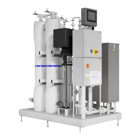
12. COMPONENT IDENTIFICATION Touch Screen Display Feed Water Tank Emergency Stop Electrical Panel RO Modules (membranes in housings) High Pressure Pump 98-0157 Rev K... -
Page 89: Appendix
13. APPENDIX 13.1 DEFAULT SETTINGS LIST FOR SINGLE AND DUAL PASS MediQA SINGLE PASS: MediQA Settings SPH RO Supply Alarm Setup Setting Default Initial Setup User Setting Units Setting Default Initial Setup User Setting Units Auto Flush Tank Quality Warning 1100 Auto Rinse Min Tank Quality Alarm... - Page 90 DUAL PASS: MediQA Settings DPH RO Supply Flow Regulation Setting Default Initial Setup User Setting Units Setting Default Initial Setup User Setting Units Auto Flush R01 Concentrate offset 217.3 Auto Rinse Min R01 Concentrate Gain 1.132 Auto Rinse Max R02 Concentrate Offset Target Recovery Stage 1 R02 Concentrate Gain 3.487...
-
Page 91: Ifu - Updating Mitsubishi Fx3G Plc Software With The Fx3G-Eeprom-32L Module
13.2 IFU – Updating Mitsubishi FX3G PLC Software with the FX3G- EEPROM-32L Module (IFU # 98-9078A) BACKGROUND: The Mitsubishi FX3G-EEPROM-32L module offers a means of updating the Mitsubishi FX3G PLC software without the need of a PC, programming cabling or special software. PROCEDURE FOR SOFTWARE UPDATING: WARNING: This procedure requires that the electrical panel door be open while power is on. - Page 92 20. Verify the PLC Run Status LED is ON. 21. Shut and secure the panel front door. 22. Navigate to the unit’s SOFTWARE VERSIONS HMI screen. Verify that the PLC software version matches the version upgrade documentation. NAMES AND FUNCTIONS OF PARTS: [1] PLC Power Status LED: Illuminated green while power is on the PLC.
- Page 93 [1] Front Cover: Can be used to remove module from PLC. [2] [WR] Pushbutton: Initiates module writing to PLC. [3] [WR] LED: Writing indicator. 98-0157 Rev K...
-
Page 94: Ifu - Updating Mitsubishi Got1000 Hmi Software W/Jump Drive
A customer can perform the upgrade, without an onsite field service tech from AmeriWater Inc. being present. The USB port for the HMI is currently brought out to the front of the control panel as an access point. - Page 95 2. Plug the Jump Drive into the USB port 3. Press the Upper Left Corner of the Touch Screen. The Screen should change to the following: 98-0157 Rev K...
- Page 96 4. Press the Icon for Program/data control. The screen will switch to the following: 5. Press the P icon for Project Information. The Screen will switch to the following: 98-0157 Rev K...
- Page 97 6. Press E: USB Drive. The screen will switch to the following: 7. Press the Download Button. The screen will switch to the following: 98-0157 Rev K...
- Page 98 8. Press OK Button. The screen will switch to the following: 9. When the download is complete the screen will automatically switch to the following: 98-0157 Rev K...
- Page 99 10. Press the OK button. The screen will change to the following: 11. The screen is now rebooting and will be back in operation with an updated program. Pull the jump drive from the USB port and store it as a backup. 98-0157 Rev K...
- Page 100 Chloride, a compound used to produce Polyvinyl Chloride (PVC). The AmeriWater system you have purchased may contain PVC or stainless steel parts. While warnings are only required in the State of California, AmeriWater has initiated the use of Prop 65 labeling for all products to ensure compliance with California regulations. Please note that the above warning does not necessarily mean that the product that you have purchased is unsafe.
Need help?
Do you have a question about the MediQA MSP Series and is the answer not in the manual?
Questions and answers