Table of Contents
Advertisement
Quick Links
Advertisement
Table of Contents

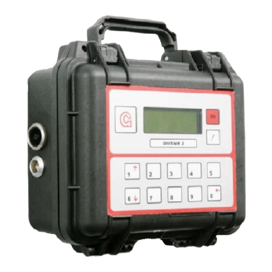
Summary of Contents for LANDTEC GEOTECH DIVEAIR 2
- Page 1 DIVEAIR 2 Diving air analyser OPERATING MANUAL Geotechnical Instruments (UK) Ltd Sovereign House Queensway Leamington Spa Warwickshire CV31 3JR England Tel: +44 (0)1926 338111 Fax: +44 (0)1926 338110 Email: sales@geotech.co.uk www.geotech.co.uk...
-
Page 2: Table Of Contents
CORRECT AND SAFE USE OF THE INSTRUMENT INTRODUCTION Physical Characteristics of the Analyser NORMAL USE Switching on Switching off Keys Connecting gas supply Types of sample hose Gas Read Screen Alarms Peak readings Batteries 2.10 External power 2.11 Pump ADVANCED FEATURES Main Menu Calibration 3.2.1... -
Page 3: Correct And Safe Use Of The Instrument
Correct and safe use of the Instrument In this manual a warning sign as below indicates important instructions that if not observed may result in damage to the instrument. Follow instructions to prevent damage to the instrument Introduction The Geotechnical Instruments range of gas analysers are sensitive pieces of scientific equipment, and should be treated as such. -
Page 4: Normal Use
Normal Use 2.1 Switching on Switch on the Diveair by pressing the red [on] key. If required the display contrast can be adjusted by means of the scroll keys (1 and 6 ) before entering the main gas reading screen. It is possible to return to this screen at any time by pressing key ‘0’ from the main gas screen. -
Page 5: Alarms
2.7 Alarms Whilst in the main gas screen the analyser monitors the gases levels and will alarm if any of the pre-set levels are triggered. The alarm consists of an alarm light on the top of the instrument, an audible beep and an indication on the LCD display. -
Page 6: Advanced Features
Advanced Features 3.1 Main Menu The main menu is pass-code protected to prevent access to the advanced features by un-trained operators. After pressing key 1-Menu from the main gas screen the analyser will prompt for a pass-code. Enter ‘0102’ and press key ‘0’ to confirm. If entered correctly the main menu will be displayed otherwise you will be returned to the main gas screen. -
Page 7: Span Gas Composition
3.2.2 Span gas composition All channels of the analyser can be span calibrated by using a single gas mixture. The default gas composition has been specified as follows :- 1000 ppm 20 ppm Isobutylene 10 ppm Balance However these can be changed by the operator to match exactly with the certified calibration gas supplied. -
Page 8: Alarm Settings
3.3 Alarm Settings Whilst in the main gas screen the analyser monitors the gases levels and will alarm if any of the pre-set levels are triggered. The alarm can be set as either latching or non latching. 3.3.1 Setting alarm limits From the main menu press key ‘2-Alarm settings’... -
Page 9: Internal Voc Filter
3.5 Internal VOC filter VOCs can affect the reading from the CO sensor. To get over this problem the Diveair analyser has a filter to remove the VOCs before the gas reaches the CO sensor. The filter is situated within the monitor and should not normally need replacing between services. -
Page 10: Replacement Of The Oxygen Cell
4.4 Replacement of the Oxygen Cell 1. Ensure the monitor is switched off. 2. Remove the 2 security tags, open the 2 latches on the monitor and open the case. 3. Un-latch the inline oxygen cell connector. 4. Carefully unscrew the oxygen cell c/w o ring from the manifold (you may need to partially loosen the oxygen cell with a pair of grips) whilst also supporting the manifold with your other hand. -
Page 11: Specification
Specification 5.1 Physical and Environmental Dimensions Height 240mm, Width 270mm, Depth 125m Weight Approx. 2.8Kg (readout only, excluding inlet/outlet fittings) Material Polypropylene Temperature 0 ºC to 50 ºC Relative humidity 0 – 100% non condensing (ambient) Sealing Splash proof 5.2 Batteries and Charger Charge time approx. -
Page 12: Oxygen Sensor
5.7 Oxygen Sensor Type Acid electrolyte Range Range 0-21% calibrated. Will read up to 100% Resolution 0.1% Repeatability ±2% of reading or ±0.2% – whichever is greater (within 30 minutes) Accuracy ±4% of reading or ±1% by volume – whichever is greater, over measurement and temperature ranges within 8 hrs of calibration T90 Response Time Approx. -
Page 13: List Of Detected Vocs
List of detected VOCs The Diveair analyser will detect all VOCs with an ionisation potential less than 10.6eV. The table below lists common VOCs that will be detected, together with their ionisation potential. The analyser is calibrated for isobutylene. * Indicates chemicals with ionisation potentials less than 10.6 but that have exhibited other properties that restrict their detection capabilities. - Page 14 Chemical Chemical Dihydropyran 8.34 Iodine 9.28 Diiodomethane 9.34 Iodo(1)-2-methylpropane 9.18 Diisopropylamine 7.73 Iodobenzene 8.73 Dimethoxyethane(1,1) 9.65 Iodobutane(1) 9.21 Dimethoxymethane Iodobutane(2) 9.09 Dimethyl acetamide Iodopentane(1) 9.19 Dimethyl ether Iodopropane(1) 9.26 Dimethyl phthalate 9.64 Iodopropane(2) 9.17 Dimethyl sulfide 8.69 Iodotoluene(m) 8.61 Dimethyl(2,2) butane 10.06 Iodotoluene(o) 8.62...
- Page 15 Chemical Chemical Methylcyclohexene(4) 8.91 Valeraldehyde 9.82 Methyl-n-amyl ketone Vinyl acetate 9.19 Methylpentane(2) 10.12 Vinyl bromide Methylpentane(3) 10.08 Vinyl chloride Monomethyl hydrazine 7.67 Vinyl methyl ether 8.93 Monomethylaniline 7.32 Vinyl toluene Morpholine Xylene(m) 8.56 Naphthalene 8.12 Xylene(o) 8.56 Nickel carbonyl 8.27 Xylene(p) 8.45 Nitric oxide(NO)
-
Page 16: Disposal Of Instrument
Disposal of Instrument WEEE COMPLIANT The wheelie bin symbol now displayed on equipment supplied by Geotechnical Instruments signifies that the apparatus must not be disposed of through the normal municipal waste stream but through a registered recycling scheme. The Waste Electrical and Electronic Equipment directive (WEEE) makes producers responsible from July 2007 in meeting their obligations, with the fundamental aim of reducing the environmental impact of electrical and electronic equipment at the end of its life.


Need help?
Do you have a question about the GEOTECH DIVEAIR 2 and is the answer not in the manual?
Questions and answers