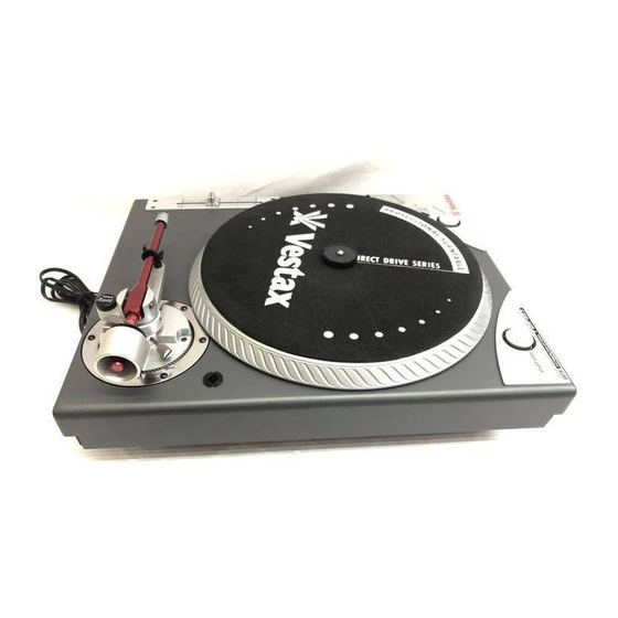
Summary of Contents for Vestax PDX- a2
- Page 1 VESTAX SERVICE NOTE MODEL: PDX- a2 1. BLOCK DIAGRAMM P. 2 2. ADJUSTMENT PROCEDURE P. 3 3. SCHEMATIC DIAGRAM P. 4 3. PARTS LIST P. 5- P. 9 4. PCB ASSEMBLEY P. 10 Vestax Corporation Service Department (2001.06.08)
- Page 3 PDX a2 Adjustment manual 1. Temperature Sensor Comparative Voltage Adjustment Measurement Point TP-4 (VC) TP-I(GND) Adjusting Point R351 (470ohm Cermet Trimmer Measurement Equipment : DC Millivoltmeter (input impedance I00K ohm ) Setting Conditions Power on. Turntable stopped. Adjustment Sequence : Power on.


Need help?
Do you have a question about the PDX- a2 and is the answer not in the manual?
Questions and answers