Future Design VR18 User Manual
Paperless recorder
Hide thumbs
Also See for VR18:
- Procedure of replacing (3 pages) ,
- Quick start manual (2 pages) ,
- Installing and removing (5 pages)
Table of Contents
Advertisement
Quick Links
Advertisement
Table of Contents

Related Manuals for Future Design VR18

Summary of Contents for Future Design VR18
- Page 1 User Manual Paperless Recorder VR18 Future Design Controls, Inc. 7524 West 98 Place Bridgeview, IL 60455 888.751.5444 - Office: 888.307.8014 - Fax 866.342.5332 - Technical Support http://www.futuredesigncontrols.com/ VR18 Manual – v2.2 – January 2006 FDC-UMVR181M...
-
Page 2: Table Of Contents
4.1 Channel (Analog input, Digital input, Analog output, Math input) ------------ 4.2 Display --------------------------------------------------------------------------- 4.3 Tools (Timer, Counter & Totalizer) ------------------------------------------------- 4.4 Instrument ------------------------------------------------------------------------- 4.5 Clock --------------------------------------------------------------------------------------- 4.6 Security & FDA 21 CFR Part 11 Features-------------------------------- 4.7 Demo -------------------------------------------------------------------------- 4.8 System Info ------------------------------------------------------------------------------ VR18 Manual V2.2 Jan 2006.doc... - Page 3 5.3 RS 232, RS485, RS422 Configuration ------------------------------------------------ 5.4 CF card Configuration ------------------------------------------------------- 5.5 Configuration in Real-Time Viewer -------------------------------------------- 5.6 DDE dynamic data exchange --------------------------------------------- 6. Application examples -------------------------------------------------------------------- 7. Trouble shooting -------------------------------------------------------------------------- 8. FAQs frequently asked questions -------------------------------------------------- VR18 Manual V2.2 Jan 2006.doc...
-
Page 4: Safety
The protection provided by the recorder may be impaired if it is used in a manner inconsistent with its intended purpose, or in an environment that exceeds the specifications of the recorder. Future Design Controls, Inc. is not liable for customer’s failure to comply with these requirements. -
Page 5: Safety Notes And Precautions
The power-line fuse is located within the fuse-holder on the power board. For 90-250 VAC line voltages, the user must use a 2.5A/250VAC time-lag fuse, and for both 11-18 VDC and 18-36 VDC line voltages, a 5.0A/250VAC time-lag fuse must be used. VR18 Manual V2.2 Jan 2006.doc... -
Page 6: General Description
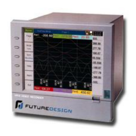
1. General Description 1.1 Unique features of recorder The VR18 is a well-designed paperless recorder with many outstanding features including: • 6.1” TFT Color LCD with VGA Display; 640 x 480 pixel resolution, 256 colors. • 1 to18 isolated Analog Inputs •... -
Page 7: Storage Media Cf Card
The IR Sensor used in conjunction with the screen saver is a user configured to be on or off. VR18 Manual V2.2 Jan 2006.doc... -
Page 8: Ordering Codes And Accessories
1: Free basic software Observer I for non-communication application 2: Extensive software Observer II for communication of RS-232/422/485 or Ethernet Firmware 0: Basic function 1: Mathematics, Counter & Totalizer & FDA 21 CFR part 11 features VR18 Manual V2.2 Jan 2006.doc... - Page 9 7: options 1 + 5 8: options 1 + 6 9: options 1 + 5 + 6 X: other options See Accessories & Notes on ordering components or model configurations not defined by matrix above VR18 Manual V2.2 Jan 2006.doc...
- Page 10 The basic PC software Observer I is supplied free with recorder. There is an additional charge for the extensive PC software Observer II for use with RS-232/422/485 or Ethernet communications. The Ordering Code for VR18 without any option is VR18-4X00-010-110 VR18 Manual V2.2 Jan 2006.doc...
-
Page 11: Specifications
(32 ~ 3308 ˚F) 0 ~ 1768 ˚C ±2 ˚C 2.2MΩ (32 ~ 3214 ˚F) 0 ~ 1768 ˚C ±2 ˚C 2.2MΩ (32 ~ 3214 ˚F) -250 ~ 1300 ˚C ±1 ˚C 2.2MΩ (-418 ~ 2372 ˚F) VR18 Manual V2.2 Jan 2006.doc... - Page 12 Integral Linearity Error: ±0.005% of Span Temperature Effect: ±0.0025% of Span /˚C 24VDC Auxiliary Power Supply Card (AP181) Channels: to be used for 6 transmitters Output Rating: 24 ± 1 VDC, 180mA in maximum, 30mA / each channel VR18 Manual V2.2 Jan 2006.doc...
- Page 13 CE: EN61010-1 (IEC1010-1) over voltage category II, Pollution degree 2 Protective Class: IP 30 front panel for indoor use, IP 20 housing and terminals EMC: Emission: EN61326 (EN55022 class A, EN61000-3-2, EN61000-3-3) Immunity: EN61326 (EN61000-4-2, EN61000-4-3, EN61000-4-4, EN61000-4-5, EN61000-4-6, EN61000-4-8, EN61000-4-11) VR18 Manual V2.2 Jan 2006.doc...
-
Page 14: Installation And Wiring
20 ~ 80 % RH (non-condensing) Power 90 ~ 250 VAC, 50/60 Hz 11-18 VDC or 18 - 36 VDC Panel mounting style Front View 166 Millimeters equals 6.53 Inches 144 Millimeters equals 5.67 Inches Figure 2 - 1 VR18 Manual V2.2 Jan 2006.doc... - Page 15 (standard DIN size 138 mm x 138 mm) (5.43” x 5.43”) Figure 2 - 3 Note: Do not over tighten mounting clamp screws that could result in distortion of the case. There is no mounting angle restriction. VR18 Manual V2.2 Jan 2006.doc...
- Page 16 Firstly, put the right ear FV-R on the right hand side of metal case, and slide it into the case by pushing in direction as shown in Figures 2-4 through Figure 2-8. Ensure that the ear is firmly plugged into case. Do the same with the left ear FV-L. Figure 2 - 4 Figure 2 - 5 VR18 Manual V2.2 Jan 2006.doc...
- Page 17 Figure 2 - 6 Figure 2 - 7 Figure 2 - 8 VR18 Manual V2.2 Jan 2006.doc...
- Page 18 Figure 2-10 and 2-11. Lastly, slide both feet beneath the case and straighten up the stoppers as Figure 2-12 and Figure 2-14. The bench top recorder is now mechanically ready. Figure 2 - 9 VR18 Manual V2.2 Jan 2006.doc...
- Page 19 Figure 2 - 10 Figure 2 - 11 VR18 Manual V2.2 Jan 2006.doc...
- Page 20 Figure 2 – 13 Figure 2 – 14 Note: To change the bench top into panel mount. Disassemble kit MK184 (one handle, two feet, and two ears) in reverse of above, and then fit the mounting clamps. VR18 Manual V2.2 Jan 2006.doc...
-
Page 21: Setup Input, Output & 24Vdc Power Supply Cards
Figure 2–15, plug it into the rear slot and then power on. The recorder will automatically detect the card and display the specific input type, then show its source of a specific slot in Configuration Mode. All inputs were initially set for 4-20mA from the factory. Figure 2 – 15 VR18 Manual V2.2 Jan 2006.doc... - Page 22 They are used to retransmit process value to another device. 24 VDC auxiliary power supply card (AP181) This card can supply the power to 6 transmitters. The output rating is 24 ± 1 VDC, 180 mA in maximum, 30mA / each transmitter. VR18 Manual V2.2 Jan 2006.doc...
-
Page 23: Wiring Of The Cards
12-channel analog input needs 4 pieces of 3-channel analog input card AI183. Now it is left 2 empty Slots for other cards. ▲ Power should be turned off while inserting input and output cards. VR18 Manual V2.2 Jan 2006.doc... - Page 24 Analog input cards (AI181, AI182, AI183) Figure 2 – 18 Analog input cards (AI181V, AI182V, AI183V) Figure 2 – 19 Digital output card (DO181) Figure 2 – 20 VR18 Manual V2.2 Jan 2006.doc...
- Page 25 Digital input card (DI181) Figure 2 – 21 Analog output card (AO183I & AO183V) Figure 2 – 22 VR18 Manual V2.2 Jan 2006.doc...
-
Page 26: Rs-232, Rs-422, Rs-485 Wiring
24 VDC auxiliary power supply card (AP181) Figure 2 – 23 2.5 RS-232, RS-422, RS-485 wiring Figure 2 – 24 VR18 Manual V2.2 Jan 2006.doc... - Page 27 Figure 2 – 25 Figure 2 – 26 VR18 Manual V2.2 Jan 2006.doc...
-
Page 28: Installation Of Compact Flash Cf Card
2.6 Installation of Compact Flash CF card A 32MB Compact Flash Card is installed in each VR18. If a larger capacity Compact Flash card is required, and the user decides to buy it locally, please check the brand name of CF card. To be compatible, it should be one of two recommended brands SanDisk or Transcend. -
Page 29: Basic Operation
Dump, Clear, Operate, Config and Shutdown. These eleven soft keys are used for operation. On the top right side, small icons of buzzer, evnt, mem, CF and Date/Time display. Figure 3 – 1 VR18 Manual V2.2 Jan 2006.doc... -
Page 30: Mode
Bar: Press Mode key again, to display bars in different colors. The scale of each bar can be defined individually, details in 4.2 Display. Digital: Press Mode key again, to display digits in different colors. Press Mode key again, to return to the original Mix mode. VR18 Manual V2.2 Jan 2006.doc... -
Page 31: History
Zoom key to zoom in the time scale. The Zoom can be done variously in 1 sec/dot, 1 hour/Page, 12 hours/Page, 1 day/Page or 1 week/Page. Press Back key going back to the original display. Figure 3 – 3 VR18 Manual V2.2 Jan 2006.doc... -
Page 32: Event
After the cause of alarm is no longer met and the alarm is acknowledged, then the red buzzer icon disappears. When Clear Time shows Terminated indicates turning off the power to the recorder has terminated the alarm. VR18 Manual V2.2 Jan 2006.doc... -
Page 33: Status
Counter and Totalizer. Press Mode key to choose any mode of DI, DO, Counter or Totalizer. Display shows the status DI, DO, Counter or Totalizer at the present time. Counter and Totalizer are available if the option of Math, Counter & Totalizer was included in the part number matrix. VR18 Manual V2.2 Jan 2006.doc... -
Page 34: Exit
3.10 Shutdown Accidental turning off the power will cause loss of data and will interrupt the operation of the recorder. Therefore press the Shutdown key to shutdown the system first before turning off the power. VR18 Manual V2.2 Jan 2006.doc... -
Page 35: Small Icons
CF card is inserted in the recorder and its memory is full, then the memory of CF card remains unchanged and the earliest measured data and events on the recorder will be overwritten and replaced by the latest measured data and events. Date/Time: To set the local time, please refer to 4.5 Clock. VR18 Manual V2.2 Jan 2006.doc... -
Page 36: Configuration
Load: Load configuration from storage media CF card to recorder. (Recorder configuration can be saved to CF card either through Observer I / II software or downloaded to the CF card from another VR18.) Default: If the configuration is set incorrectly, Default is a useful key to recall the default settings on the analog input card inserted into rear expansion slot. -
Page 37: Channel (Analog Input, Digital Input, Analog Output, Math Input)
Average: logging in averaged measured data at the sampling interval Minimum: logging in minimum measured data at the sampling interval Maximum: logging in maximum measured data at the sampling interval VR18 Manual V2.2 Jan 2006.doc... - Page 38 Each pen can accept four events (or alarms) and each event can create two jobs. Please note that a job under Event is different from a job by pressing the VR18 Manual V2.2 Jan 2006.doc...
- Page 39 ◆ Press Back key to return to real-time display, all configurations will be memorized ◆ The Digital output DO card with 6 relays can be set in Job1, Job2. It can be traced in System Info mode after installed into the Slot. VR18 Manual V2.2 Jan 2006.doc...
- Page 40 Press AO key to select the Analog output. Define 0-20mA or 4-20mA if it is current output card AO183I. Define 0-5V, 1-5V or 0-10V if it is voltage output card AO183V. Then define Expression and range. VR18 Manual V2.2 Jan 2006.doc...
- Page 41 ▲ To add the optional Math module (includes Counter & Totalizer features) in the field it is necessary to order a Boot ROM with this option. Then, open the housing and replace the Boot ROM. VR18 Manual V2.2 Jan 2006.doc...
- Page 42 Channel column of Pen 4, then select MATH1. Define Color, Width of trend, DisplayHi and DisplayLo. Press the Back key twice to return to the beginning of display all configurations will be memorized; then the Math starts working. VR18 Manual V2.2 Jan 2006.doc...
-
Page 43: Display
Color: Selects the color for each pen. Width: Selects the width of trend, 1-thin, 2-medium, 3-wide. Low: Defines the low scale for a pen on the display. High: Defines the high scale for a pen on the display. VR18 Manual V2.2 Jan 2006.doc... - Page 44 0-10V, Scale Low=0.00, Scale Hi=100.00, to have better resolution and vision on Bar, set DisplayLo=0.00, DisplayHi=50.00 so that the Bar displays from value 0.00 to 50.00. ◆ The decimal point is defined by Scale Hi and Scale Low, and not by DisplayHi, or DisplayLo. VR18 Manual V2.2 Jan 2006.doc...
-
Page 45: Tools (Timer, Counter & Totalizer)
Repeat Countdown: Repeats the previous countdown. Daily, Weekly or Monthly: The timer works in selected interval of Real Time. Action: Disables or enables the timer. Job1, Job2: various jobs as described in 4.1 Channel, 2 jobs for each timer. VR18 Manual V2.2 Jan 2006.doc... - Page 46 Time – Hour: 17 Min: 01 Job1: Log Report Target: AI1 MinMaxAve (to AI6 MinMaxAve) Job2: Reset MinMaxAve (Reset historical data in order to logging new data for the next day.) Figure 4 – 7 VR18 Manual V2.2 Jan 2006.doc...
- Page 47 Type: Select one of three options: None, Process Hi, Process Low Setpoint: Defines the set point of process value to trigger the counter. Job1, Job2: various jobs as described in 4.1 Channel, 2 jobs for each counter VR18 Manual V2.2 Jan 2006.doc...
- Page 48 Type: Select one of three options: None, Process Hi, Process Low Setpoint: Defines the set point of process value to trigger the totalizer. Job1, Job2: various jobs as described in 4.1 Channel, 2 jobs for each totalizer. VR18 Manual V2.2 Jan 2006.doc...
- Page 49 Log Alarm Set DO off The Weekly Report shows the following information: The week’s production volume: Monday: 990, Tuesday: 1010, Wednesday: 1020, Thursday: 1020, Friday: 980 respectively. The weekly report shows production volume 5,020. VR18 Manual V2.2 Jan 2006.doc...
-
Page 50: Instrument
Time limit during operation; 10 minutes since last key action requires the user to key in password again. Audit trail function to record the user, time and what operator actions. Details explained in 4.6 Security & FDA 21 CFR part 11 Features. VR18 Manual V2.2 Jan 2006.doc... - Page 51 RS-232, RS-485, RS-422: Address: 0 to 247 nodes for RS-485 Baud Rate: Selects it from various Baud rates 1200, 2400, 4800, 9600, 19200, 38400, 57600 or 115200. Data Format: Selects it from three different data formats. VR18 Manual V2.2 Jan 2006.doc...
- Page 52 ▲ If Automation is selected, the IP address and SubnetMask are invisible. IP address can be found in 4.8 System Info under Configuration. Because IP address might be reallocated with new address by the server after power off and on, the user defining fixed addresses is recommended. VR18 Manual V2.2 Jan 2006.doc...
-
Page 53: Clock
Date/Time: Set up the local time. Use directional keys going to the Apply column, and then press the Enter Key to apply it to the recorder. Summer time / Daylight Savings: Summer time / Daylight Savings may be enabled and set to occur at specific dates. Figure 4 – 11 VR18 Manual V2.2 Jan 2006.doc... -
Page 54: Security & Fda 21 Cfr Part 11 Features
Supervisor: Access all the keys but no authority to define the user names. Operator: Access to vertical keys to view the historical data, events and status, but no authority to access horizontal keys to do configuration, dump or clear data. VR18 Manual V2.2 Jan 2006.doc... -
Page 55: Demo
Memory (Free / Total): Indicates the percentage of free memory to total memory reserved on the recorder. 8 MB memory on board is reserved for storing measured data. A small icon on the top right indicates the percentage of free memory e.g.: mem 96%. VR18 Manual V2.2 Jan 2006.doc... -
Page 56: A Configuration Example
Update: The Update key is located at left lower side. It is the key to upgrade new firmware. After the new firmware is downloaded from a PC to the CF card insert the CF card in the VR18 CF slot. Then press this key to upgrade it. -
Page 57: Pc Software And Communication Configuration
5. PC software and Communication configuration 5.1 Observer I & Observer II PC software guide Observer I & II software are used in conjunction with the VR18 to archive, analyze measured data from the recorder and to do recorder configuration through PC. - Page 58 This is to remove Observer software from PC. Observer I or Observer II may be uninstalled from PC any time from the following two ways Control panel- Add/remove programs-observer I/observer II Start –Programs-Observer I / Observer II / Uninstall VR18 Manual V2.2 Jan 2006.doc...
- Page 59 Send configuration (CF card/RS 232/Ethernet) If Observer software is already configured in the PC, select *.prj file to see a listing of all projects. For the first time configuration you can cancel the above window and select new project VR18 Manual V2.2 Jan 2006.doc...
- Page 60 2. Ethernet 3. RS 232 32 MB CF card shall be supplied along with the recorder. Standard Ethernet port (RJ 45 female) shall be available at the recorder. RS 232/ RS485 is offered as an option. VR18 Manual V2.2 Jan 2006.doc...
-
Page 61: Ethernet Configuration
5. Two different types of cables shall be used for connecting the recorder on Ethernet as follows. For connecting the recorder to LAN HUB, then standard straight-through Ethernet cable should be used. For connecting the recorder to PC/Notebook directly, then a crossover Ethernet cable must be used. VR18 Manual V2.2 Jan 2006.doc... - Page 62 7. If the communication between the recorder and PC/LAN HUB is successful, then start Observer II in the PC as follows Start-Programs-Observer II – Configuration For the first time, Under Historical folder .prj file shall not be available. Open new file Enter new name for the project, i.e. “Boiler” VR18 Manual V2.2 Jan 2006.doc...
- Page 63 Select Ethernet in the Bank by using radial button Open for Ethernet connection Enter the IP address of the Recorder System will ask “Do you want to receive configuration data now? (Y/N)” Click on “Yes” to upload the recorder configurations to PC. VR18 Manual V2.2 Jan 2006.doc...
- Page 64 Contact Network/ System administrator for proper Ethernet configuration of the recorder & PC. Please note that recorder should have unique IP address in the network and PC being used for Observer II shall have separated Unique IP address in the network. VR18 Manual V2.2 Jan 2006.doc...
-
Page 65: Rs 232, Rs485, Rs422 Configuration
5.3 RS 232, RS485, RS422 Configuration It is possible to use PC software Observer II for data logging from multiple VR18 recorders connected on network RS 485. Total number of devices that can be connected depends on the hardware interface selected for the application. - Page 66 10. Click on “Yes” to upload the recorder configurations to PC. 11. If Upload is successful, it shows message as “Configuration successful” and all the configuration settings of VR18 recorder now available at PC. The information includes all channel details of Input/Output cards as per Jumper/switch settings on each module.
- Page 67 In some computers, COM 1 and COM 2 have been used for other devices. So it is required to carefully check whether RS 232 cable is connected to proper communication port of PC or not. VR18 Manual V2.2 Jan 2006.doc...
- Page 68 If above conditions are not met, then RS 232 port is having problem at PC. Contact system administrator for replacing the port or updating driver properly. If communication is still not established, user can try setting up Observer software in another PC where the COM port is performing properly. VR18 Manual V2.2 Jan 2006.doc...
- Page 69 Make sure that RS 232 communication setting at the recorder and PC are set with the same values. VR18 Manual V2.2 Jan 2006.doc...
-
Page 70: Cf Card Configuration
4. Once the PC detects CF reader along with CF card it will appear as removable drive at the computer. 5. Start Observer program, Ex: Start-Programs-Observer 1 - Configuration Open new file Enter new name for the project, i.e. “Boiler” 6. Select CF card using radial button VR18 Manual V2.2 Jan 2006.doc... - Page 71 If still problem exists, check the files available in the CF card at PC. At least 2 files by name IO and RECORDER should be available. If the files are not available, then recorder configuration data is not properly saved in the CF card. Repeat process starting at Step 2. VR18 Manual V2.2 Jan 2006.doc...
-
Page 72: Configuration In Real-Time Viewer
If auto-update option is selected in modify tag data as shown in following screen, then all the settings done at the channel for events will appear here. If it is not selected, then user can configure manually for different set points in order to generating alarm emails. VR18 Manual V2.2 Jan 2006.doc... - Page 73 The Email on event will be received like this, Type: HiAlarm Source: AI1 ActiveTime: 12/12/20059:49:59AM Value: 23.8 Option: Three options of Share, Email and Communication are to be defined. It is mainly to set email configuration and real time log speed. VR18 Manual V2.2 Jan 2006.doc...
- Page 74 60 seconds. When recorder and Observer are separated in far distance, it is preferable to use Ethernet option so that it can have better data transfer rate for communication. VR18 Manual V2.2 Jan 2006.doc...
- Page 75 If you change the port number in Observer you cannot establish communication between Observer and Recorder. Port no: 502 is used to establish communication between recorder and Observer software to exchange data on Ethernet over Modbus TCP protocol. VR18 Manual V2.2 Jan 2006.doc...
-
Page 76: Dde Dynamic Data Exchange
Observer software and Excel using DDE link. Open real time viewer from start – programs – Observer II – Real-time viewer Project – create DDE link in excel Specify the path and file name as follows. VR18 Manual V2.2 Jan 2006.doc... - Page 77 DDE expression format to get real time data from the Observer software is as follows. =RealTime_Viewer|TagService!_AI1 Application = RealTime_Viewer Topic = TagService Tag name = AI1 VR18 Manual V2.2 Jan 2006.doc...
- Page 78 DDE link once again and open the Excel file. 2. Increase virtual memory in the PC. Please contact system administrator to check the virtual memory settings in the PC in following steps. My computer-properties-advanced-performance settings –advanced-virtual memory. VR18 Manual V2.2 Jan 2006.doc...
- Page 79 'open dde link: testsol=DDE Topic This is comment only RSIchan = DDEInitiate ("RSLinx", "DDE_REPORTS") 'write data thru channel This is comment only DDEPoke RSIchan, "F8:2,L10", Range ("[Reports.XLS]PROCESS!D37:D46") 'close dde link This is comment only DDETerminate (RSIchan) End Sub VR18 Manual V2.2 Jan 2006.doc...
- Page 80 'get data and store in data variable. This is comment only data = DDERequest(RSIchan, "N7:30,L5,C1") 'Paste data into selected range. This is comment only Range("[Reports.XLS]DDE_Sheet!A7:A11").Value = data 'close dde link. This is comment only DDETerminate (RSIchan) End Sub VR18 Manual V2.2 Jan 2006.doc...
- Page 81 Procedure for configuration 1) Open SCADA project 2) System – Node – Select DDE server as data source 3) Name = VR18 (No gaps) 4) Application = RealTime_Viewer 5) Topic = TagService 6) Check enable in the box. (This node should be selected) 7) Now open the data base 8) Create analog tag with all the details similar to the tag at the recorder.
-
Page 82: Application Examples
Job 1: Start logging Job 1: Stop logging Timer 3 Timer 4 Type: Weekly Action: Enable Type: Weekly Action: Enable Time: Saturday 8 Hour 1 Min Time: Sunday 8 Hour 1 Min Job1: Stop logging Job1: Stop logging VR18 Manual V2.2 Jan 2006.doc... -
Page 83: Trouble Shooting
7. Trouble shooting VR18 Manual V2.2 Jan 2006.doc... - Page 84 VR18 Manual V2.2 Jan 2006.doc...
- Page 85 VR18 Manual V2.2 Jan 2006.doc...
-
Page 86: Faqs Frequently Asked Questions
The temperature inside the housing has an effect on accuracy of Real Time Clock of crystal oscillator. Temperature range Time lag per month 10 ~ 40 ˚C 18 seconds 0 or 50 ˚C 52 seconds -10 or 60 ˚C 107 seconds VR18 Manual V2.2 Jan 2006.doc... - Page 87 Internet or CF card. To add Math and/or High Security features the BT181 chip must be replaced with the BT182; these chips are socket mounted. Q8: How are the VR18 recorder firmware & PC Observer software upgraded to latest version? If necessary, contact your supplier about the latest updates or visit our website http://www.futuredesigncontrols.com.
- Page 88 Q17 Is the recorder supplied with OPC server? A17: The OPC server is not available in the VR18. However Observer II PC software does offer DDE solution to allow data transferred to other devices like PLC, SCADA etc. Please review a few examples in 5.5 DDE dynamic data exchange.
- Page 89 CF card memory size: 32MB 256MB Log speed 1 second 30 days 240 days 960 days 10 seconds 300 days 2400 days 9600 days 120 seconds 3600 days 28800 days 115200 days VR18 Manual V2.2 Jan 2006.doc...
- Page 90 Then, install the new Observer software from CD supplied. If the problem still can’t be solved, then uninstall the old Observer software and create a back up for the historical and real-time folders under C:/Observer and remove Observer folder from C: Then install the new Observer software again. VR18 Manual V2.2 Jan 2006.doc...
- Page 91 A possible solution is to use an external converter for the application. The standard pulses to 4-20mA converters are available in the market where you can set pulse width and duration between pulses (frequency). VR18 Manual V2.2 Jan 2006.doc...
- Page 92 Future Design Controls facilities and to conform at that time to the specifications set forth in the relevant Future Design Controls manual, sheet or sheets for a period of Two years after delivery to the first purchaser for use.
Need help?
Do you have a question about the VR18 and is the answer not in the manual?
Questions and answers