Table of Contents
Advertisement
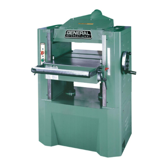
SETUP & OPERATION MANUAL
FEATURES
Positive gear design for quick and accurate
table adjustments.
5" dust collection hood.
Cast-iron table and head.
Four cutter knives result in easier cutting and
longer motor life, (helical cutter head model
available: #30-360HC).
Built-in table rollers reduce friction.
Large 8" handwheel quickly adjusts table
height.
Comes with magnetic safety switch.
Graduated scale in both inches and metric to
indicate workpiece thickness.
Anti-kickback fingers at the front of the infeed
roller to ensure maximum operator safety.
Vertical adjustment handle for table rollers.
Equipped with a sectioned infeed roller and a
rubber outfeed roller.
One front-mounted exterior table roller.
SPECIFICATIONS
• Table size
32" x 20" (813 x 508 mm)
• Maximum planing width
20" (508 mm)
• Min/Max thickness of stock
3/16" (5 mm) / 8" (204 mm)
• Minimum length of stock
8 1/4" (210 mm)
• Maximum cutting depth (full width)
1/8" (3 mm)
• Maximum cutting depth (width 8 1/2" or less)
1/4" (6 mm)
• Cutter head diameter
3 3/4" (97 mm)
• Cutter head speed
4500 rpm
• Feed speeds
(2) 22 & 28 fpm
• Cuts per inch (not applicable for HC model)
68.17 at 22 fpm & 53.5 at 28 fpm
• Number of knives / Inserts
4 - 30-360 / 58 - 30-460HC
• Base dimensions (l x w)
36" x 22" (914 x 559 mm)
• Motor
M1: 7 1/2 HP , 220 V, 1 Ph, 31 A
M2: 7 1/2 HP , 220 V, 3 Ph, 20 A
M3: 7 1/2 HP , 600 V, 3 Ph, 10 A
• Weight
1392 lbs (633 kg) - 30-360
1397 lbs (635 kg) - 30-360HC
Version
1_Revision
2 - November 2015
#
#
© Copyright General International
20" SINGLE SURFACE PLANER
MODEL
30-360
#
30-360HC*
#
*With helical cutter head
Advertisement
Table of Contents

Related Manuals for General 30-360

Summary of Contents for General 30-360
- Page 1 68.17 at 22 fpm & 53.5 at 28 fpm MODEL • Number of knives / Inserts 4 - 30-360 / 58 - 30-460HC • Base dimensions (l x w) 36” x 22” (914 x 559 mm) *With helical cutter head •...
- Page 2 GENERAL® INTERNATIONAL 8360 Champ-d’Eau, Montreal (Quebec) Canada H1P 1Y3 Telephone (514) 326-1161 • Fax (514) 326-5555 • www.general.ca THANK YOU for choosing this General® International model 30-360/30- 360HC 20” single surface planer. This planer has been carefully tested and inspected before shipment and if properly used and maintained, will provide you with years of reliable service.
- Page 3 2 years (24 months) from the date of purchase. General® International agrees to repair or replace any part or component which upon examination, proves to be defective in either workmanship or material to the original purchaser during this 2-year warranty period, subject to the “conditions and exceptions”...
-
Page 4: Table Of Contents
Periodic maintenance ............................. 19 Inspecting cutter head knives/inserts ......................19 Inspecting cutter head (model 30-360 only) ....................20 Knife setting or replacement (model 30-360 only) ..................21 Helical cutter head insert reversal/Replacement (model 30-360HC only) ..........22 Replacing the gear box ........................... 23 Lubrication ................................. -
Page 5: Rules For Safe Operation
11. Always use clean, properly sharpened knives. Dirty 23. Do not use this planer for any purpose other than or dull knives are unsafe and can lead to accidents. its intended use. If used for other purposes, General ® International disclaims any real or implied warranty 12. -
Page 6: Electrical Requirements
ELECTRICAL REQUIREMENTS BEFORE CONNECTING THE MACHINE TO THE POWER SOURCE, VERIFY THAT THE VOLTAGE OF YOUR POWER SUP- PLY CORRESPONDS WITH THE VOLTAGE SPECIFIED ON THE MOTOR I.D. NAMEPLATE. A POWER SOURCE WITH GREATER VOLTAGE THAN NEEDED CAN RESULT IN SERIOUS INJURY TO THE USER AS WELL AS DAMAGE TO THE MACHINE. -
Page 7: Identification Of Main Parts And Components
IDENTIFICATION OF MAIN PARTS AND COMPONENTS FRAME EXTENSION ROLLER ON/OFF SWITCH MAIN TABLE DUST CHUTE GRADUATED SCALE FEED SPEED ADJUSTMENT KNOB DEPTH OF CUT ADJUSTMENT HANDWHEEL ECCENTRIC BLOCK EXTENSION ROLLER LOCK LEVERS (2) TABLE ROLLER ADJUSTMENT LEVER... -
Page 8: Unpacking
The unit is offered with 2 different cutter head options as follows: • Model 30-360 M1 – 20” planer with 4-knife cutter head; • Model 30-360HC M1 - 20” planer with General International’s unique “Magnum” style helical cutter head con- taining 58 reversible two-sided, quick-change carbide inserts. -
Page 9: Cleaning
CLEANING The protective coating on the table prevents rust from forming during shipping and storage. Remove it by rubbing with a rag dipped in kerosene, mineral spirits or paint thinner. (Dispose of potentially flammable sol- vent-soaked rags according to manufacturer’s safety recommendations). -
Page 10: Attach The Depth Of Cut Adjustment Handwheel
Check that all connections are sealed tightly to help minimize airborne dust. If you do not already own a dust collection system consider contacting your General® International distributor for information on our complete line of dust collection systems and ac- cessories or visit our Web Site at www.general.ca. -
Page 11: Basic Adjustments And Controls
BASIC ADJUSTMENTS & CONTROLS TO REDUCE THE RISK OF SHOCK OR FIRE DO NOT OPERATE THE UNIT WITH A DAMAGED POWER CORD OR PLUG. RE- PLACE DAMAGED CORD OR PLUG IMMEDIATELY. TO AVOID UNEXPECTED OR UNINTENTIONAL START-UP , MAKE SURE THE POWER SWITCH IS IN THE OFF POSITION BEFORE CONNECTING TO A POWER SOURCE. -
Page 12: Adjusting Table Roller Height
The height of the rollers can be set based on personal preference as well as the type of stock being fed into the machine. As a general rule when planing rough stock the rollers should be set higher, and when planing smooth stock they should be set lower. -
Page 13: Operating Instructions
OPERATING INSTRUCTIONS BASIC PRINCIPLES OF PLANING ALWAYS PLANE IN THE GENERAL DIRECTION OF THE GRAIN. PLANING AGAINST THE GRAIN OR PLANING END GRAIN IS DANGEROUS AND MAY CAUSE THE WORKPIECE TO SHATTER. This planer is designed to remove material from the top... -
Page 14: Adjusting The Depth Of Cut
ADJUSTING THE DEPTH OF CUT The depth of cut is adjustable by using the handwheel A. Remind that the maximum depth of cut on full width planing is 1/8” and lowering the head assem- bly. It is recommended that for both hard and soft wood: removing less material per pass and taking multiple passes is always preferred to more aggressive planing. -
Page 15: Planing Step By Step
Align the board laterally so that it will be fed through Slowly slide the workpiece forward until the infeed the planer in the general direction of the grain, and roller “grips” the board. allow the workpiece enough clearance to feed properly without rubbing or catching on either side of the machine. -
Page 16: Maintenance
You may use a home made gauge block made of hardwood. The gauge block can be made by follow- ing the dimensions in the illustration. If you prefer, precision aluminum gauge blocks are available from General International under item #30-040. 1½"... -
Page 17: Adjusting The Infeed & Outfeed Rollers
MAKE SURE THE MACHINE HAS BEEN TURNED OFF AND UNPLUGGED FROM THE POWER SOURCE BEFORE PERFORM- ING ANY MAINTENANCE OR ADJUSTMENTS. ADJUSTING THE INFEED & OUTFEED ROLLERS REAR VIEW Begin by take note of all the components in order Place the gauge block E under the knife/insert C, to make required adjustments: A infeed roller;... -
Page 18: Adjusting The Chipbreaker
MAKE SURE THE MACHINE HAS BEEN TURNED OFF AND UNPLUGGED FROM THE POWER SOURCE BEFORE PERFORM- ING ANY MAINTENANCE OR ADJUSTMENTS. ADJUSTING THE CHIPBREAKER (CONTINUED) Loosen the two jam nuts M using a 10 mm wrench. Turn the set screws N using a 4 mm Allen key in the direction required so that the chipbreaker (see ref- erence B in a previous page) touches the top of the block. -
Page 19: Periodic Maintenance
(sold in sets of 10) can be ordered through your local General International distributor under part #30-362 or #30-364 (for model 30-360) or 30-443 (for model 30- 360HC). Observing planed workpieces as they come out of the machine and looking for signs of knife dam- age or wear is the best method to help you to deter- mine when knives/insertions are due to be changed. -
Page 20: Inspecting Cutter Head (Model 30-360 Only)
MAKE SURE THE MACHINE HAS BEEN TURNED OFF AND UNPLUGGED FROM THE POWER SOURCE BEFORE PERFORM- ING ANY MAINTENANCE OR ADJUSTMENTS. INSPECTING CUTTER HEAD KNIVES (MODEL 30-360 ONLY) Note: To make sure the knives are properly adjusted, use the jig provided to check each of the four knives. -
Page 21: Knife Setting Or Replacement (Model 30-360 Only)
MAKE SURE THE MACHINE HAS BEEN TURNED OFF AND UNPLUGGED FROM THE POWER SOURCE BEFORE PERFORM- ING ANY MAINTENANCE OR ADJUSTMENTS. KNIFE SETTING OR REPLACEMENT (MODEL 30-360 ONLY) Properly setting all four knives is essential to achieving accurate results. Properly set knives will last longer and also keep their edge (sharpness) longer by equally sharing the cutting workload. -
Page 22: Helical Cutter Head Insert Reversal/Replacement (Model 30-360Hc Only)
To maintain even insert wear always reverse or replace all 58 inserts each time knife replacement is required. When needed, replacement inserts B can be ordered through your local General International distributor under part #30-443 (sold by sets of ten). -
Page 23: Replacing The Gear Box
Important! The nut and screw that secures the knife-holder/chip breakers and inserts in the cutter head does not have to be removed for blade reversal/replacement, only loosened. If the nuts and screws have to be replaced or if they have been removed instead of loosened, follow the instructions below to make sure that the knife-holder/chip breakers are all secured at the same height into the cutter head. -
Page 24: Lubrication
MAKE SURE THE MACHINE HAS BEEN TURNED OFF AND UNPLUGGED FROM THE POWER SOURCE BEFORE PERFORM- ING ANY MAINTENANCE OR ADJUSTMENTS. LUBRICATION LUBRICATION REFERENCE CHART PART REFERENCE TYPE OF LUBRICANT FREQUENCY TASK ELEVATION SCREWS ALL PURPOSE GREASE ONCE A MONTH SLIDING SURFACES ALL PURPOSE OIL ONCE A MONTH... -
Page 25: Cleaning Anti-Kickback Fingers
MAKE SURE THE MACHINE HAS BEEN TURNED OFF AND UNPLUGGED FROM THE POWER SOURCE BEFORE PERFORM- ING ANY MAINTENANCE OR ADJUSTMENTS. CLEANING ANTI-KICKBACK FINGERS The anti-kickback fingers on this planer are designed to reduce the risk of injury due to kick-back by prevent- ing the workpiece from being violently ejected from the machine. -
Page 26: Adjusting Belt Tension/Changing The Belts
MAKE SURE THE MACHINE HAS BEEN TURNED OFF AND UNPLUGGED FROM THE POWER SOURCE BEFORE PERFORM- ING ANY MAINTENANCE OR ADJUSTMENTS. ADJUSTING BELT TENSION/CHANGING THE BELTS Inspect the belts afler every 100 hours of use. Belts that show visible signs of wear such as cracks or fraying at the edges should be replaced immediately. -
Page 27: Recommended Optional Accessories
RECOMMENDED OPTIONAL ACCESSORIES Here is a sampling of optional accessories available from your local General International dealer that can be used with this product. For more information about our products, please visit our website at www.general.ca DUST COLLECTORS Item #50-150/ 167S/170... -
Page 28: Parts List & Diagram
DIAGRAM HEAD - 30-360... - Page 29 DIAGRAM FRAME - 30-360...
- Page 30 DIAGRAM TABLE - 30-360...
- Page 31 DIAGRAM STAND - 30-360...
- Page 32 LOCK WASHER 8.2X15.4 30360-47 HEX HEAD BOLT M5X0.8PX12L 30360-105 CAP SCREW M8X1.25PX25L OR #360H 30360-48 CUTTERHEAD 30360-106 WASHER 8.5X16X2T FOR 30-360 FOR 30-360HC 30360-49 BEARING 6006-2NSE 30360-107 LEFT SIDE COVER 30360-50 GEAR 30360-108 LEFT SIDE SUPPORT COVER 30360-51 SET SCREW M10X1.5PX12L...
- Page 33 30360-189 ADJUSTMENT HANDWHEEL 30360-131 HANDLE 30360-190 HANDLE 30360-132 WASHER 4.3X10X1.0T 30360-191 FIXING PLATE 30360-133 M10X1.5P 30360-192 CAP SCREW M10X1.5PX20L 30-360-133-1 KNOB 30360-193 HANDLE 30360-134 FIXING PIN 30360-194 SHAFT 30360-135 SHAFT 30360-195 FIXING PLATE 30360-136 SPROCKET 30360-196 CAP SCREW M8X1.25PX45L 30360-137...
- Page 34 ALLEN KEY 30360-274 ALLEN KEY 30360-249-1 SPROCKET WASHER 5.3X10(BW-5) 30360-275 ALLEN KEY 30360-250 TERMINAL PLATE 30360-276 KNIFE SETTING JIG BAR (30-360 ONLY) 30360-251 ROUND HEAD SCREW 3/16-24NCX1/4” 30360-277 KNIFE SETTING JIG PAD (30-360 ONLY) 30360-252 TERMINAL COVER 30360-278 RETENTION RING...
- Page 35 WIRING DIAGRAM 30-360 M1...
- Page 36 WIRING DIAGRAM 30-360 M2...
- Page 37 WIRING DIAGRAM 30-360 M3...
-
Page 38: Contact Information
8360 Champ-d’Eau, Montreal (Quebec) Canada H1P 1Y3 Tel.: (514) 326-1161 Fax: (514) 326-5565 - Parts & Service / (514) 326-5555 - Order Desk orderdesk@general.ca www.general.ca Follow us:...
Need help?
Do you have a question about the 30-360 and is the answer not in the manual?
Questions and answers