Table of Contents
Advertisement
Quick Links
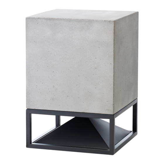
CUBE400 SERVICE MANUAL
0.0 > Tools:
prepare the following tools on a work surface
A _
B _
Cutter
2 Allen Key
#3 and #7
0.1 > Set Up:
before start working on the Cube, carefully follow these steps:
In case the Cube comes with concrete
de ector, make sure to remove it before
overturning it. Pay attention not to scratch the
legs during this operation.
1.0 > Disassembly Procedure:
C _
D _
Phillips
2 Flat
Screwdriver
Wrenches #17
Turn the cube upsidedown on a soft
surface (base facing up), ...
1 >
Using the Cutter (A) remove the
net protecting the cable by cutting the
heat-shrinking sheath locking it it, and
leave the cable naked.
3 >
Using the Allen Key #3(B)
unscrew the 4 M5X30 screws and
remove the stainless steel frame
protecting the coaxial. The coaxial
remains untied as well.
E _
F _
Torque
Welder
Wrench #7
(40 W min)
.. possibly using the original protective
packaging, to avoid possible scratches.
G _
Hot
Air Gun
2 >
Using the Allen Key #7(B) unscrew
the 4 M10 screws securing the base,
making sure to always unscrew the
screw opposite to the previous one and
paying attention not to scratch the legs.
Lift the base and at the same time pull
out the cable from the column holding it
vertically to facilitate the movement of
the base.
4 >
Lift the coax and turn it over the
inner ange of the Cube. Desolder the
quadripolar
cable
from
connections on the coaxial speaker,
quickly enough to avoid thermal damage
to wires and internal connections of the
driver. Be sure to remember the colors of
the phases. (Brown > +Woofer; Green >
-Woofer; Yellow > +Tweeter; White >
-Tweeter)
H _
2 Nylon
Cable Ties
the
four
Advertisement
Table of Contents

Related Manuals for ARCHITETTURA SONORA CUBE400


Summary of Contents for ARCHITETTURA SONORA CUBE400
- Page 1 CUBE400 SERVICE MANUAL 0.0 > Tools: prepare the following tools on a work surface 2 Nylon Cutter 2 Allen Key Phillips 2 Flat Torque Welder Cable Ties #3 and #7 Screwdriver Wrenches #17 Wrench #7 (40 W min) Air Gun 0.1 >...
- Page 2 5 > Remove the coax. Remove the 6 > silicone holding the cable into its Remove the acoustic dumper disc and appropriate groove carved into the take out the acoustic foam “candy” that Cube’s body. Slip the bipolar cable out contains the crossover IP65 waterproof box.
- Page 3 bipolar cable quadripolar cable 3 > Insert the perimeter acoustic dumper groove for cable on body inside the cube, making sure to reinsert it behind the port tubes of the Cube, then insert the rst acoustic dumper ring. Place the crossover box “candy”, complete perimeter with cables, inside the Cube, positioning it acoustic dumper...
- Page 4 2.1 > Crossover Board Assembly: 1 > Place the board inside the box and secure it to the box by screwing the four star screws (X), paying attention not to force the plastic thread. 2 > Arrange the internal wires according to the attached image, in order to avoid inappropriate contacts between wiring and crossover components.
- Page 5 11 > Insert the cable in the through Grower column of the base and at the same time washer (I) place the base on the Cube taking extre- Flat steel me care not to scratch the frame below. washer (L) IMPORTANT: the cable was previously laid Red ber washer (M)
- Page 6 3.7 > Upgrade a Cube with the “Light Mood” base. 1 > 1 > 2 Follow steps of “1.0 Disassembly Procedure” to remove the “standard base” of your Cube. 2 > The “Lighting Mood” base comes already cabled for the electical part, with net protecting the cable locked with heat-shrinking sheaths, ready to be installed.
Need help?
Do you have a question about the CUBE400 and is the answer not in the manual?
Questions and answers