Table of Contents
Advertisement
Advertisement
Table of Contents

Subscribe to Our Youtube Channel
Related Manuals for Imada ZTS Series


Summary of Contents for Imada ZTS Series
- Page 1 Dinamómetro Digital Serie ZTS...
- Page 2 Digital Force Gauges with Electro Luminescent (EL) Display Multi-Language Menus and ZT Logger Data Acquisition Software Standard Models: ZTS, ZTS-DPU, ZTS-LM INSTRUCTION MANUAL 07/18 V339644...
-
Page 3: Table Of Contents
INTRODUCTION ..........3 PRECAUTIONS . -
Page 4: Introduction
NEVER exceed 200% of the rated capacity, or the load cell will be damaged. Avoid shock load. 3. When mounting ZTS Series, use M4 mounting screws with a maximum insertion depth of 5 mm into the gauge. For high capacity gauges use the supplied mount- ing hardware only. -
Page 5: Overview
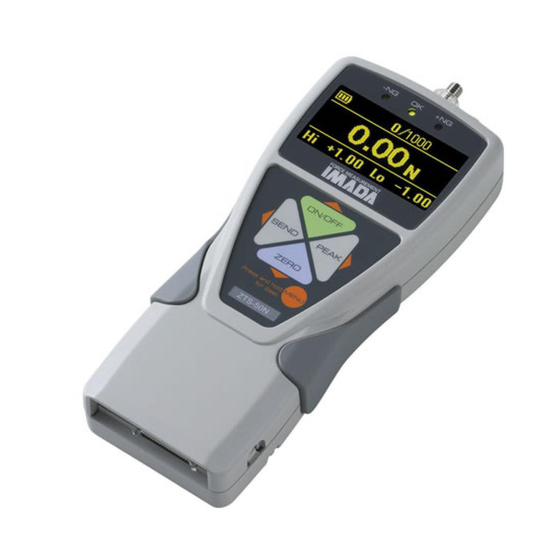
OVERVIEW MULTI DISPLAY Upper Section Battery status indicator Auto zero icon: appears when Auto Zero is set. Select data: Date, Time, Stored memory data, Measurements over high setpoint (see pages 32-33). Middle Section Peak indicator Force value Units See page 37 to switch between Multi and Single display. -
Page 6: Preparation
ON/OFF 1. Push to turn off power. 2. Only use IMADA AC adapter/charger (ADW6010) with the proper 115VAC or 230VAC plug adapter. Plug into the correct AC output. Turn ON the gauge. The display flashes until the battery is charged. -
Page 7: Common Programming Tasks
COMMON PROGRAMMING TASKS 1.Date and Time Program Menu (optional) Display Functions ON/OFF 1. Press to turn ON the Date and Time > gauge, then press and hold High Low Setpoints MENU two seconds to enter the Program Menu. Press the Date &... -
Page 8: Selecting Units
2.Selecting Units Setup Menu Language MENU 1. Turn OFF the gauge. Press and hold Units > ON/OFF then press to turn ON the gauge +/- Indicator and enter the Setup Menu. Units is highlighted, press the right arrow key to select. Units 2. -
Page 9: Programming Go/No Go Setpoints
4.Programming Setpoints (optional) Program High and Low setpoints for easy Go/No Go testing. ON/OFF 1. Press to turn on the gauge. Program Menu MENU 2. Press and hold the key two Date and Time High Low Setpoints > seconds to enter the Program Menu. Peak Functions 3. -
Page 10: Setting Lock
5.Setting LOCK Setup Menu (optional) Language Prevents gauge settings from being changed. Setting LOCK > MENU 1. Turn OFF the gauge. Press and hold Units ON/OFF then press to turn ON the gauge and enter the Setup Menu. Setting LOCK 2. -
Page 11: Programming
1.Programming Select units, reverse display and set the high/low setpoints if required, using the steps on pages 6-9. 2.Attachments Hand tighten attachments to the shaft. Do not use tools! 3.Measurement Mode Real Time Measurement ON/OFF Press to turn on the gauge. The gauge automatically enters real time mode and displays transient force values. -
Page 12: Storing And Collecting Data
STORING AND COLLECTING DATA SEND Press during measurement, in Peak or Real Time mode, to store a value. Up to 1,000 force values may be stored in gauge memory. SEND Press when gauge and PC are connected with included USB cable and data is stored in gauge memory and transmitted to the PC. -
Page 13: Downloading Data From Memory
All Data Delete 1. Follow Recalling Stored Data steps 1-3, page 11. 2. Highlight Data Delete and press the right arrow key. 3. Press the up/down arrow keys and select All Data Delete. MENU 4. Press the key to clear and a confirmation screen MENU appears. -
Page 14: Optional Data Acquisition Accessories
ON/OFF 5. External Power ON/OFF (Same as key function) Connecting #24 (EX_Power) and #30 (GND) of the communications port turns ON the gauge and connecting #24 (EX_Power) and #30 (GND) while #29 (Shift) and #30 (GND) are connected turns OFF the gauge. ZERO 6. -
Page 15: Output
OUTPUT 37 PIN CONNECTOR 1.Communications Port PIN# Signal Description -NG Output Signal (Note 1) OUTPUT CONNECTION OK Output Signal (Note 1) +NG Output Signal (Note 1) 25mA Over Load Output (Note 1) READY Output while Measuring (Note 1) OUT_GND Signal ground for Pins 1 to 7 ANALOG OUT 2 Direct Analog Output (Optional) ANALOG GND 2... -
Page 16: Data Output Formats
2.Data Output Formats Data Output Format [Q][±fffff][±ddddddd][P][L][C][S][X][CR] Memory Data Output Format m[±fffff][±ddddddd][P][L][C][S][YY][MM][DD][hh][mm][ss][CR] Type of Data f: Continuous data output (2000 data/sec) I: Continuous data output (10 data/sec) a: Continuous +peak data h: Continuous –peak data Type of Data r: Real time data p: +Peak n: –Peak 1: 1st Peak... - Page 17 4.Command Table (RS232C & USB communication) CATEGORY COMMAND DESCRIPTION RESPONSE NOTES XAR[CR] Real Time Data Output Request XFP[CR] +Peak and –Peak Data Output Request See Data Output Format Data Output XFF[CR] 1st Peak and 2nd Peak Data Output Request Data Output XAg[CR] Continuous Data Output Request (10 data/sec) XAG[CR]...
- Page 18 5.Backward Compatible Command Table (RS232C & USB communication) CATEGORY COMMAND DESCRIPTION RESPONSE NOTES FFFFF: Force Data w/ Decimal Point Data Output Request D[CR] [±FFFFF][U][M][C][CR] U: Unit, K (Kgf), N (N) or O (Lbf) Data Output M: Mode, T (Real time), P (Peak) D[CR] Data Output Request [±FFFFF][U][M][C][CR]...
-
Page 19: Zt Logger
4. Find the force gauge in the Device Manager. It will be under “Other Devices”. The force gauge will be listed as an "Unknown Device" or "Imada ZT Series". Right click the entry and select "Update Driver Software..." in Windows 7 and "Update Driver" in Windows 10."... - Page 20 8. To confirm the driver is installed. Open the Device Manager and Expand the “Ports COM & LPT” Tab. You should see an entry for “IMADA ZT Series” page 21...
- Page 21 Windows 8 Driver Settings Before installing the Windows 8 driver, Start the installation of unsigned drivers in Windows 8 must be enabled. Follow the Tiles steps below. Help 1. Activate the charm bar, hover over the bottom right or top right corner of the screen, then press the Settings Icon.
- Page 22 You should see Microsoft .NET Framework X.X. 2. If you do not see Microsoft .NET Framework 4.0 you will need to install it from the CD-ROM included with your Imada ZTS force gauge. Open the CD in Window Explorer and navigate to ZT Logger/Non-...
-
Page 23: Operation
2.ZT Logger Operation 1. Connect the ZTS force gauge and computer with the USB cable. 2. Turn ON the gauge. 3. Click Start/All Programs/Imada/ZT Logger and start ZT Logger If Indicator doesn’t change to Connect, check: USB cable USB driver installation Microsoft .NET Framework 4.0 installation. - Page 24 Zero Button Zero the force value on the force gauge Peak Capture peak value Zero Both Button Zero both force and displacement values on the force gauge Capture Value Button Captures and displays data in table Start Continuous Capture Start capturing continuous data at 10 data/second max.
- Page 25 Basic Operation 1. Display Setup Click on Display and check the data items to appear in the data table and to save in CSV files. * Displacement is only available with ZTA force gauges 2. Zero Reset ZERO Click on the button to zero force or displacement values.
- Page 26 4. Trigger Setup Click on Data/Trigger Setup, to set the trigger values (force/dis- placement) for automatic acquisition. Enter trigger values in the fields (absolute values only) and check the force/displacement boxes to activate the trigger. When the force/displacement value exceeds the trigger value, the force/displacement is automatical- ly captured and displayed in the data table.
- Page 27 Saving Data The Data Table can be saved in CSV format and imported into Microsoft Excel and Word. * Check items to save in the Display Menu. * Data may not appear correctly in Microsoft Excel depending on the Excel settings. 1.
- Page 28 ZTS Force Gauge Settings 1. ZTS force gauge setup Click on Gauge Setup Menu/Gauge Setup to show the Program and Setup menus. Changes made in this window also change the force gauge settings. Click Close to complete settings. To set up High/Low Setpoints, Output and thresholds, enter the value with decimals displayed on the force gauge without deci-...
- Page 29 10/second Data Processing Speed Actual 2,000 data/second through the USB port Power Rechargeable Ni-MH battery pack or Imada ADW6010 adapter Battery Indicator Indicates three charge states high, medium and low Battery Life approx. 8 hours (recharge time approx. 10 hours) Operating Temp.
- Page 30 ZTS DIMENSIONS 75 (2.95") (1.33") (.47") Measuring Shaft: Up to 110 lbf: 10-32 220 lbf: M6 4-M4 (2.51") (1.22") (1.57") ZTS HIGH CAPACITY DIMENSIONS Models: ZTS-550 & ZTS-1100 52 (2.04") (.98") 4-M10 x 1 M16 x 1.5 44.5 (3.26") (1.75") (11.14") High Capacity with handles page 31...
-
Page 31: Using Multi Display
REFERENCE SECTION — MULTI DISPLAY Using Multi Display Multi Display (factory default) divides the screen into three sec- tions: upper, middle and lower. Selectable data can be displayed in the upper and lower sections. See the next page for Single Display. Upper Section Turn on the gauge, then press (do not hold) the MENU... - Page 32 REFERENCE SECTION — MULTI DISPLAY When memory number/value are highlighted, press (do not hold) MENU key and the data location number becomes highlighted. ON/OFF ZERO Press the up ( ) or down ( ) arrow keys to view other locations and values if more than one are stored. If no data is stored MENU ‘–’...
- Page 33 REFERENCE SECTION — PROGRAM MENU High Low Setpoints Program Menu Date and Time High/Low setpoints enable Go/No Go tests. Orange High Low Setpoints > LED lights for values under the low setpoint (–NG), Peak Functions green lights for values within low and high (OK), and red lights for values over high (+NG).
- Page 34 REFERENCE SECTION — PROGRAM MENU Auto Peak Memory Factory Default=‘OFF’ ZERO Sends peak value to memory when is pressed. MENU 1. Turn ON the gauge. Press and hold two seconds to enter the Program Menu. Press down arrow key to highlight Peak Functions then press the right arrow key to select.
- Page 35 REFERENCE SECTION — PROGRAM MENU Program Menu Auto Zero Timer Factory Default=‘OFF’ Internal Memory Automatically clears peak value. appears when set. Auto Zero Timer > Select: 1~60 seconds or OFF. Sound MENU 1. Turn ON the gauge. Press and hold seconds to enter the Program Menu.
-
Page 36: Display Functions
REFERENCE SECTION — PROGRAM MENU Program Menu Display Functions Sound Display Format Factory Default=‘Multi’ Display Functions > Single Display displays force value, unit, peak and Date and Time battery indicators. Multi Display divides the screen into three sections. Top section displays date, time, data storage, or +NG count. Middle section displays unit and value. - Page 37 REFERENCE SECTION — PROGRAM MENU Program Menu Display Functions (continued) Sound Reverse Display Factory Default=‘Normal’ Display Functions > Invert the screen so it can be read when the Date and Time gauge is mounted to a test stand. Select: Normal or Reverse. MENU 1.
-
Page 38: Date And Time
REFERENCE SECTION — PROGRAM MENU Program Menu Date and Time Display Functions Date Set Date and Time > MENU 1. Turn ON the gauge, then press and hold High Low Setpoints two seconds to enter the Program Menu. Press the down arrow key to highlight Date and Time, then press the right arrow key to select. -
Page 39: Setup Menu
REFERENCE SECTION — SETUP MENU Setup Menu Units Language Select: lbf (ozf), N, kgf (gf) Units > Factory Default=‘lbf’ +/- Indicator MENU ON/OFF 1. Press and hold , then press to turn ON the gauge and enter the Setup Menu. Units is high- lighted, press the right arrow key to select. -
Page 40: Sensitivity
REFERENCE SECTION — SETUP MENU Setup Menu Sensitivity +/- Indicator Some applications may yield more consistent Sensitivity > results with less sensitivity. Zero/Tare Reset Select: Max, High, Medium, Low Factory Default=’Max’ (best for destructive tests) MENU ON/OFF 1. Press and hold , then press to turn ON the gauge and enter the Setup Menu. -
Page 41: Send Functions
REFERENCE SECTION — SETUP MENU Setup Menu Send Functions Zero/Tare Reset SEND Store current value(s) in memory when Send Functions > pressed. Date Format Select: Display Value, + Peak, – Peak, +/– Peak Factory Default=‘Display Value’ MENU ON/OFF 1. Press and hold , then press to turn ON the gauge and enter the Setup Menu. -
Page 42: Language
REFERENCE SECTION — SETUP MENU Setup Menu Language Date Format Select: English, Chinese, Korean, German, French, Language > Italian, Spanish, Japanese Units Factory Default=‘English’ MENU ON/OFF 1. Press and hold , then press to turn ON the gauge and enter the Setup Menu. Press the down arrow key to highlight Language, then press the right arrow key to select. - Page 43 PRODUCTS EXPRESSLY NOT COVERED BY WARRANTY: Batteries, cables, attachments, adapters, and fixtrures regardless of the manufacturer of the product, that are sold or provided for by Imada are not covered by the foregoing warranties. Warranties of the respective manufacturers for such products shall apply.
Need help?
Do you have a question about the ZTS Series and is the answer not in the manual?
Questions and answers