Table of Contents
Advertisement
Quick Links
DVE10
DRIVER'S VISIoN ENhANCER MoNIToR SERIES
USER MANUAL
10.4" TFT rugged LCd dispLay
DIGITAL SYSTEMS ENGINEERING, INC. (DSE)
17491 NOrTH 93rd sTreeT | sCOTTsdaLe, aZ 85255
DSE SERVICE CENTER:
480-515-1110
SERVICE@DIGITALSYS.COM
|
WWW.DIGITALSYS.COM
© 2017 by digiTaL sysTems eNgiNeeriNg. aLL rigHTs reserved.
Advertisement
Table of Contents

Subscribe to Our Youtube Channel
Related Manuals for DIGITAL SYSTEMS ENGINEERING Driver's Vision Enhancer Monitor Series

Summary of Contents for DIGITAL SYSTEMS ENGINEERING Driver's Vision Enhancer Monitor Series
- Page 1 DRIVER’S VISIoN ENhANCER MoNIToR SERIES USER MANUAL 10.4" TFT rugged LCd dispLay DIGITAL SYSTEMS ENGINEERING, INC. (DSE) 17491 NOrTH 93rd sTreeT | sCOTTsdaLe, aZ 85255 DSE SERVICE CENTER: 480-515-1110 SERVICE@DIGITALSYS.COM WWW.DIGITALSYS.COM © 2017 by digiTaL sysTems eNgiNeeriNg. aLL rigHTs reserved.
- Page 2 NOT eNdOrsemeNTs. COpYRIGhT THis dOCumeNT CONTaiNs prOprieTary iNFOrmaTiON prOTeCTed by COpyrigHT. aLL rigHTs are reserved. NO parT OF THis maNuaL, iN wHOLe Or parT, may be reprOduCed by aNy meaNs, iN aNy FOrm, wiTHOuT priOr wriTTeN permissiON OF digiTaL sysTems eNgiNeeriNg.
- Page 3 DVE10 DRIVER’S VISIoN ENhANCER MoNIToR SERIES USER MANUAL 10.4" TFT rugged LCd dispLay © 2017 by digiTaL sysTems eNgiNeeriNg. aLL rigHTs reserved. um-dve10 (F) 4/17...
-
Page 4: Table Of Contents
DVE10 SERIES TAbLE oF CoNTENTS introduction ..................5 general safety.................. 6 electrical safety ................7 product Care and maintenance ............8 system set-up .................. 9 installation ..................10 pressure equalizer valve ..............11 display Connectors ................ 12 Operator Controls ................16 appendix a - mechanical drawings .......... -
Page 5: Introduction
The dve10 display can easily be installed in a standard a-kit mount, and is fully backwards compatible with existing dve installations, making it suitable for any tactical vehicle application. we are digital systems engineering, keeping rugged Technology in Motion. Our digital Technology Team is at the ready to support your system projects. -
Page 6: General Safety
GENERAL SAFETY SAFETY ICoNS safety icons are inserted throughout the awm series ii user manual to draw attention to specific user Caution and warning instructions. WARNING! ShOCk hAzARDS This icon warns user of a potential risk of electrical shock. CAuTION! INSTRuCTIONAL This icon is intended to tell the user of important operating and/or maintenance instructions. -
Page 7: Electrical Safety
ELECTRICAL SAFETY ELECTRICAL INSTALLING CAbLES • pre and post installation, verify display’s power input connector is securely seated • install power cable so as not to come in contact with hot surfaces • do not allow anything to rest on power cable, and •... -
Page 8: Product Care And Maintenance
PRoDUCT CARE AND MAINTENANCE PRoDUCT CARE This dve10 display is designed to provide optimum performance and service without any required scheduled maintenance other than occasional cleaning. prior to use, remove the protective film from the display screen. DISPLAY SCREEN CLEANING The display screen is a glass-based product. -
Page 9: System Set-Up
PRoDUCT CARE AND MAINTENANCE (CoNTINUED) LoNG-TERM SToRAGE • For long-term storage, display should be stored in an ambient indoor environment • display screen be protected from accidental damage • For pedestal mount, disconnect cable(s) and loosen arm adjustment to where ball can be removed from arm, or •... -
Page 10: Installation
INSTALLATIoN The dve10 may be mounted in three configurations, decided at time of order: with a univer- sal ball-and-socket mounting kit, in a Flat panel or optional Flush mount configuration. oPTIoNAL PEDESTAL MoUNT Optional is a ram® universal ball-and-socket system mounting kit (Figure 1). by installing the display with this kit, user can adjust the viewing angle to improve viewability in chang- ing environments. -
Page 11: Pressure Equalizer Valve
INSTALLATIoN (CoNTINUED) There are three mounting holes in the back of the display for attachment of a ball mounting plate. Take care not to strip the screw holes or over tighten. (Figure 4) it is recommended the remaining ball be mounted on a flat surface. because of various surface substrates where the display is mounted, the installer provides the screws to mount the other ball. -
Page 12: Display Connectors
DISPLAY CoNNECToRS CAbLES all cables are supplied by end user; dve10 is not shipped with cables. CoNNECToRS Connectors are located on bottom of display’s rear housing (Figure 1). Looking from left to right: videO OuT (a1j5); digiTaL iNTerFaCe (a1j4), seNsOr (a1j2) bNC input: iN (a1j3) and bNC Output, OuT (a1j6) and pOwer (a1j1). - Page 13 DISPLAY CoNNECToRS (CoNTINUED) VIDEo oUT CoNNECToR (A1J5) Video oUT The military grade sealed video Out Connector (1) 3-PiN PLUG 3-pin plug allows for pass-through of sensor input MiL-dTL-38999 SerieS iii (a1j2, a1j3). see Table 2. A1J5 SIGNAL • end-user supplies cable •...
- Page 14 DISPLAY CoNNECToRS (CoNTINUED) SENSoR CoNNECToR (A1J2) SeNSor CoNNeCTor The sensor Connector (a1j2) (3) links the display to 22 PiN PLUG input from the sensor Camera system video signal. MiL-dTL-38999 SerieS i This 22-pin plug input may be simultaneous with an A1J2 auxiliary composite video signal.
- Page 15 DISPLAY CoNNECToRS (CoNTINUED) bNC CoNNECToR - oUT (A1J6) BNC CoNNeCTor - oUT The bNC Connector - Out (5) allows for pass-though of 3-PiN PLUG sensor or auxiliary composite video signal (a1j2, a1j3). A1J6 see Table 6. SIGNAL • end-user supplies bNC coaxial video cable VID_OUT CENTER •...
-
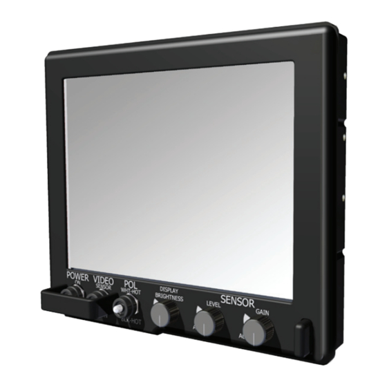
Page 16: Operator Controls
oPERAToR CoNTRoLS There are six (6) Operator Controls across bottom of display’s front bezel (Figure 2; Table 8); three (3) specifically work when receiving input from the video sensor. These controls are active based on sensor system installed. POSITION CONTROL DESCRIPTION DISPLAY POWER VIDEO POLARITY... -
Page 17: Appendix A - Mechanical Drawings
APPENDIX A MEChANICAL DRAwINGS mount diagrams and dimensions may be of assistance in installation. Overview drawings may be found on the corresponding product page on the dse website (www.digitalsys. com). when on the product page, scroll down and select the download tab and follow instructions. - Page 18 APPENDIX b (CoNTINUED) SYMPToM: DISPLAY hAS RoLLING “bARS” ACRoSS ThE SCREEN oR VERTICAL ShADED bARS oN ThE IMAGE. possible problem Solution system video display is not set to view at 800 x verify system video display is set at 800 x 600 600 pixels or 1024 x 768 pixels pixels (1024 x 768 pixels).
- Page 19 NoTES um-dve10 (F) 4/17...
- Page 20 DIGITAL SYSTEMS ENGINEERING, INC. (DSE) 17491 NOrTH 93rd sTreeT | sCOTTsdaLe, aZ 85255 DSE SERVICE CENTER: 480-515-1110 SERVICE@DIGITALSYS.COM WWW.DIGITALSYS.COM © 2017 by digiTaL sysTems eNgiNeeriNg. aLL rigHTs reserved. um-dve10 (F) 4/17...
Need help?
Do you have a question about the Driver's Vision Enhancer Monitor Series and is the answer not in the manual?
Questions and answers