Advertisement
Quick Links
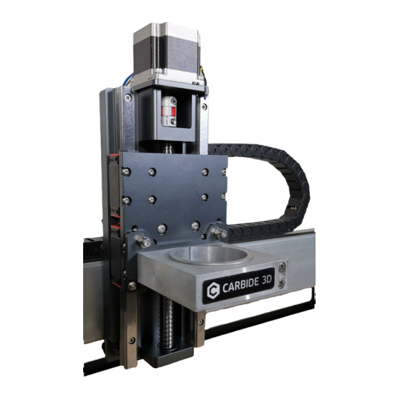
HDZ 3.3 Assembly Guide
Intro
Thank you for purchasing a HDZ. We hope you enjoy your purchase!
●
If you have any issues following these instructions please contact support@carbide3d.com.
●
Prior to fitting the HDZ, please ensure you can rotate the ball screw by hand and move the carriage to
the top and bottom of the carriage - if you cannot do this please contact us on
support@carbide3d.com.
●
If you have any issues with your HDZ upon setup such as binding or movement please contact
support@carbide3d.com
●
Note to install CM you are required to run Carbide Motion 4.17 onwards. The latest version of Carbide
Motion can be downloaded from the below link.
https://carbide3d.com/carbidemotion/download/
To carry out this modification you need basic mechanical skills and an understanding of how the Shapeoko is
assembled. The installation should take under 2 hours. You will need basic shop tools and a metric set of allen keys
and spanners (the tool kit that came with your Shapeoko should be adequate).
We have created a quick overview video which will give you an indication of the process.
Your HDZ comes 95% ready to fit, however a number of parts (listed below) will need to be transferred from your
existing Z/X axis. As of this posting the HDZ comes with replacement guide bearings and spacers. These no longer
need to be removed as stated in the video.
Please use the screws provided. Note the screws used are METRIC, usually M5.
This process is uniform across the Shapeoko 3, 3XL and 3XXL.
Once fitted please ensure GRBL settings have been changed. DO NOT HOME UNTIL THIS HAS BEEN DONE.
Your HDZ should come with green caps pre fitted to the rails - if they have not been fitted you will want to do this
yourself. You might need to use a small dab of rubber based adhesive or CA glue. In most cases, they can be pressed
in using the flat side of a screw driver.
- we request you do not attempt to diagnose or dismantle the HDZ.
https://youtu.be/ojVpMMRCeVU
Advertisement

Related Manuals for Carbide 3D HDZ 3.3


Summary of Contents for Carbide 3D HDZ 3.3
- Page 1 HDZ 3.3 Assembly Guide Intro Thank you for purchasing a HDZ. We hope you enjoy your purchase! ● If you have any issues following these instructions please contact support@carbide3d.com. ● Prior to fitting the HDZ, please ensure you can rotate the ball screw by hand and move the carriage to the top and bottom of the carriage - if you cannot do this please contact us on support@carbide3d.com.
- Page 3 Contents Each HDZ comes with the following hardware as standard (this is all required to attach it to your Shapeoko). As of October the only items you need to transfer from your existing X/Z is the homing switches, X/Z motors, spindle.motor and mount.
-
Page 4: Assembly Tip
Assembly Tip Upon assembly it’s up to you if you use thread lock we suggest adding it after if any screws become loose. If you decide to use thread lock use blue – i.e. light/medium grade. The quickest and easiest way to fit the HDZ is to assemble the majority components to the HDZ prior to fitting the HDZ to the Shapeoko. - Page 5 Z Motor and Coupling ● 4 x M5 Screw ● Z motor ● Z Motor Coupling Placing the new coupler on the ball screw slide it down as far as it goes and tighten the lower side of the coupler.
- Page 6 Slide your motor shaft onto this coupler and position the 4 x 10mm M5 screws. Tighten these in a cross pattern.
- Page 8 Once the motor is fitted, tighten the coupling at the motor side. Note you need to ensure these are tight, failure to do so will lead to slippage. A small amount of blue thread lock on the motor shaft and ball screw shaft won’t do any harm. X Pulleys and Supports ●...
- Page 9 ● 2 x M8 Washer ● 2 x M8 Spacer ● 4 x M8 Support Bearing Fit the two washers to the screws first then the 4 bearings finally finishing with the with the M8 spacers. Once the screws are assembled fit these screws to your HDZ to the two M8 holes. Fitted correctly your mounts should look like the below and the screws will not poke through the front of the plate.
- Page 10 Note the Screw head/Washer/flanged Bearings//Spacer combination.
- Page 11 X Motor Supports ● 4 x M5 25mm supports There are four threaded holes in the center of the carriage just above the M8 bolts. Insert the 4 x 25mm motor supports into the 4 holes. Please note these are aluminum. Do not over-tighten them. When the spacers have been fitted, fit your X motor using the 4 x M5 x 10mm screws provided.
- Page 12 Assembly: V-wheels 4 x V-wheels ● 4 x M5 Shim ● 4 x M5 x 25mm screw The HDZ comes with a spare set of V-wheels, you can use these or your old ones. Fit the top two V-wheels first using the provided 25mm M5 screws. Ensuring there is a shim between the back plate and the V-wheel.
- Page 13 When the top V-wheels have been fitted, lift the carriage onto the X axis beam. Then fit the bottom V-wheels in the same fashion. As you fit them ensure the V-wheel grooves are on the rail. Once fitted ensure the axis moves freely left/right. To properly seat the axis, tighten the lower M5 screws - as they tighten they will rotate the eccentrics, applying pressure to the v-wheels.
- Page 14 X Motor ● 4 x M5 x 10mm screw ● X Motor Start by threading your belt, creating a large loop, then fit your X motor using the 4 x M5 screws.
- Page 16 X Belt As the carriage is on the extrusion and the belt is in place you can re-fit the X belt. It should be taut.
- Page 17 Drag Chain Support Re-fit the drag chain support using the two M5 screws from your bracket.
- Page 18 X Homing Switch Use your existing M5 bolts and spacers to fit the X homing switch to the new carriage as before. There are two threaded M5 holes on the right-hand side of the carriage.
- Page 19 Motors Re connect your X and Z motors, ensuring each one is correct. Then tidy up your wiring.
- Page 20 Spindle Mount ● Spindle Mount & screws ● 2 x M5 x 18mm screws ● 2 x M5 x 10mm screws ● 2 x M5 non threaded eccentric nut The EZTram spindle mount is a great feature on the HDZ. It’s easy to fit and makes tramming your spindle a lot easier utilizing 2 eccentric spacers.
- Page 21 Next place the EZTram mount on the lower front of the Z axis and fit the two provided eccentric spacers to the two 18mm screws. Thread these into the holes of the HDZ. The side with the groove of the eccentric spacer indicates the lowest point. Lightly tighten the screws so the eccentric spacers can move (tramming instructions are below).
- Page 22 HD Spindle Mount If you are using one of the matching HD spindle mounts please note you do not use the EZTram plate. Also note the smaller central screw is used for opening the mount up. Once the spindle has been inserted into the mount please remove this screw and re-tighten the 4 screws to mount.
-
Page 23: Maintenance
Tramming Instructions Once your spindle has been re-fitted you can tram it using the EZTram mount. You can now tram your spindle quickly and easily. As a starting point have all your EZTram bolts finger tight. Rotate both eccentric spacers to their lowest points (slot up) then rotate to level out your Z. - Page 24 DO NOT TRY TO HOME THE SHAPEOKO OR JOG IT before applying the settings. Select your type of Shapeoko and tick the box “Use Shapeoko HDZ” then click the “Send Config Data” Button. The config data will send - wait till this has finished. As you have disconnected multiple switches it is good practice to test the homing switches.
- Page 25 Once all switches have been checked, you are ready to use your Shapeoko again! Click the “Jog” button top right and then proceed to home and use your Shapeoko with the HDZ. Happy milling!
Need help?
Do you have a question about the HDZ 3.3 and is the answer not in the manual?
Questions and answers