Advertisement
I N S T A L L A T I O N
Installations of this Vertical Rod strike qualify as "Indoor Use Only" when not continuously exposed to an outdoor
environment.
Important: Adjust strike as indicated in steps 7 & 8 to ensure proper functionality. Ensure the exit device functions as
intended for life safety concerns by verifying electric strike and exit device compatibility. Maximum latch projection is
essential to obtain full engagement.
This product is Fail Locked only. The local Authority Having Jurisdiction shall be consulted with regard to the use of
selected panic hardware to ensure emergency exit from the secured area.
Catalog Specifications
MODE
VOLTAGE CURRENT
Fail Locked
12V
Fail Locked
12V
Fail Locked
24V
Fail Locked
24V
Fail Locked
11-16V
Fail Locked = Fail Secure = FL
AC = Alternating Current
Intermittent Duty = Energized less than 1 minute with 1:5 duty ratio Continuous Duty = Energized 1 minute or more
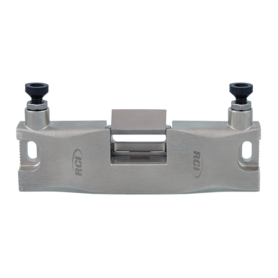
Dimensional Details
ISVR165
WWW.RUTHERFORDCONTROLS.COM • PHONE: 1.800.265.6630 • FAX: 1.800.482.9795 • E-MAIL: SALES@RUTHERFORDCONTROLS.COM
®
DUTY
AC
Intermittent
DC
Continuous
AC
Intermittent
DC
Continuous
AC
Intermittent
DC = Direct Current
3
4 "
(19.0mm)
1
1
6
8 "
5
"
2
(155.6mm)
(139.7mm)
© 2016 RUTHERFORD CONTROLS INT'L
SURFACE MOUNTED VERTICAL ROD STRIKE
PEAK AMPS
OHMS
0.20
22
0.45
22
0.48
22
0.24
89
0.18-0.27
22
3
1
"
4
(44.5mm)
5
1
8 "
(41.5mm)
HORIZONTAL
ADJUSTMENT
MOUNTING
HOLES
1
2
"
4
(57.0mm)
M8 SCREW
LOCK DOWN
CLAMP
VR165
UL 294 Performance Ratings:
Access Control Line Security : Level I
Destructive Attack : Level I
Endurance : Level IV
Standby Power : Level I
5
1
8 "
(42.0mm)
®
R09/16TG-2
Advertisement
Table of Contents

Related Manuals for RCI VR165


Summary of Contents for RCI VR165
- Page 1 I N S T A L L A T I O N VR165 SURFACE MOUNTED VERTICAL ROD STRIKE ® ® Installations of this Vertical Rod strike qualify as “Indoor Use Only” when not continuously exposed to an outdoor environment. Important: Adjust strike as indicated in steps 7 & 8 to ensure proper functionality. Ensure the exit device functions as intended for life safety concerns by verifying electric strike and exit device compatibility.
- Page 2 Instructions 1. Close the door and place the template under the retractable latch. 2. Use projection of latch to align the vertical and horizontal centerline of the strike. 3. Center punch the two mounting holes along with the wire access hole shown on the template. 4.
Need help?
Do you have a question about the VR165 and is the answer not in the manual?
Questions and answers