Table of Contents
Advertisement
Quick Links
I N S T A L L A T I O N
Pre-Installation Instructions
1.
This product must be installed according to all applicable
building and life safety codes.
2.
Due to the variety of mounting configurations available with
this product, a survey and assessment of the physical area
in which the product will be installed must be performed.
3.
The door frame must be inspected and deemed structurally
sound prior to installation of the electromagnetic lock. The
structural integrity of the mounting surfaces must be strong
enough to meet or exceed the holding force of the product.
The product must be protected from potential damage due
4.
to intruders or tampering.
The product should be installed in a location that will not
5.
hinder or create a potential safety hazard to authorized
personnel accessing the protected area.
6.
Because electromagnetic locks are used in a variety of
applications and different door frame configurations, an
experienced installer with knowledge of this product must
make a determination of the optimal mounting method for
this specific application.
7.
The components, hardware, installation instructions and
mounting template included with this product are intended
for use on outswinging doors.
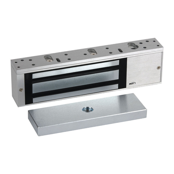
1.
Mount the electromagnetic lock to the door frame as outlined
on the installation template included with the product.
NOTE: During installation of the armature plate to the door it
is essential that the armature plate remains movable. The
armature plate must be allowed to pivot on the center-mounting
bolt to allow proper alignment with the magnet surface. If the
plate is not aligned with the magnet surface, the lock may lose
holding force or not lock at all .
The head of the armature mounting bolt ships with a rubber
washer affixed to it. This washer should project slightly beyond
the surface of the armature plate. This is to allow the washer to
expand when power is removed and break the air vacuum
between the plate and the magnet surface. If this washer is
removed or trimmed the lock will appear to have some holding
force even when power is removed.
IS8310-20
www.rutherfordcontrols.com • Phone: 1.800.265.6630 • fax: 1.800.482.9795 • e-mail: sales@rutherfordcontrols.com
PleASe DelIveR All INSTAllATIoN INSTRuCTIoNS To
tHe eND-user upoN completIoN of tHe INstallatIoN.
Do not install this product on the exterior of buildings.
8.
9.
Do not use as a doorstop. This will void warranty.
10. Separate accessories not included with this product must be
used in the following applications:
• Inswinging doors
• Narrow head jamb situations or center-hung doors
• Wherever there is insufficient space on the door
• Glass or Herculite doors that do not have a door frame
• Hollow metal or wood frames where the door stop is
• Wherever an obstruction in the door prevents
• Doors that do not permit the armature plate to be
Refer to the Product Accessories Guide section of the
Installation Instructions for further information. Accessories
may impact holding force.
11. Installation of this product should be done by an experienced
installer with knowledge of this product.
NOTE: It is highly recommended that thread locking compound
be applied to all screws during installation to reduce chance of
screws loosening over extended time.
Installation Instructions
For added safety, thread locking compound has been provided for
the armature plate bolt and the four captive electromagnetic lock
mounting screws.
WARNING: Improper installation, maintenance, inspection or
usage of the product or any related accessories or parts may
cause the electromagnetic lock, armature plate and associated
hardware to disengage and fall, causing serious bodily injury and
property damage. Rutherford Controls Int'l Inc. and/or Rutherford
Controls Int'l Corp. will not be liable to the installer, purchaser,
end user or anyone else for damage or injury to person or
property due to improper installation, care, storage, handling,
maintenance, inspection, abuse, misuse or act of God or nature
involving this product or any related accessories or parts.
2.
Route the power supply connecting wire through the door
frame and into the wire access hole in the top of the magnet
housing. Connecting wire should be of sufficient gauge for
the lock being installed and the distance being run. See table
for current draw specifications and wiring gauge chart.
© 2017 RutheRfoRd ContRols Int'l | dormakaba Group
Electromagnetic Locks
frame header to mount the lock
not thick enough to allow the product to be installed
installation of the armature plate at a proper height
mounted low enough to meet the magnet surface
8310/8320
PCN16047
R09/17GR
Advertisement
Table of Contents

Related Manuals for RCI 8310


Summary of Contents for RCI 8310
- Page 1 I N S T A L L A T I O N 8310/8320 Electromagnetic Locks PleASe DelIveR All INSTAllATIoN INSTRuCTIoNS To tHe eND-user upoN completIoN of tHe INstallatIoN. Pre-Installation Instructions Do not install this product on the exterior of buildings. This product must be installed according to all applicable building and life safety codes.
- Page 2 Delayed Relock Feature - Should the built-in delayed relock feature be required for the installation, a Normally open CORRECT Momentary switch such as an RCI 909 will need to be installed FILTERED DC SUPPLY and connected to the two blue wires from J2 on the circuit board as illustrated in Fig.1.
- Page 3 Surfaces must be cleaned periodically with a Lock Options non-abrasive cleaner. Both of the 8310 and 8320 locks can be equipped with the DSS or SCS options or both. All mounting fasteners must be inspected on a quarterly basis.
- Page 4 NOTE: All RCI electromagnetic locks must be powered with filtered and regulated DC power supplies such as the RCI 10 Series ul listed power supply. RCI offers a full line of power supplies and switching devices that are suitable for use with the 8300 Series locks.
- Page 5 8310 & 8320 Electromagnetic Lock Installation Instructions (Continued) Product Accessories Guide Accessories may impact holding force. Separate installation instructions provided with accessories. Part Usage Example Top Jamb bracket and angle bracket kit is required for use when mounting the lock on a door that swings inwards.
- Page 6 The Split Armature plates are half the length of a standard armature. each of these is Split Armature Plates mounted on one of a pair of doors with an 8310 lock centered on the frame between the doors. NOTE: use of split armature plates will reduce holding force.
- Page 7 8310 & 8320 Electromagnetic Lock Installation Instructions (Continued) WIRE GAUGE SELECTIONS Load Current @24V Total One Way 1/4A 1/2A 3/4A 1-1/4A 1-1/2A Length of Wire Run (ft.) 1000 1500 Load Current @12V Total One Way 1/4A 1/2A 3/4A 1-1/4A 1-1/2A Length of Wire Run (ft.)
- Page 8 8310 & 8320 Electromagnetic Lock Installation Instructions (Continued) Maintenance Schedule CoMPANY NAMe: DOOR LOCATION DATE NOTES INITIAL © 2017 RutheRfoRd ContRols Int’l | dormakaba Group www.rutherfordcontrols.com • Phone: 1.800.265.6630 • fax: 1.800.482.9795 • e-mail: sales@rutherfordcontrols.com...
Need help?
Do you have a question about the 8310 and is the answer not in the manual?
Questions and answers