
Related Manuals for mabe MEE09VV


Summary of Contents for mabe MEE09VV
- Page 1 MEE09VV PM01...
-
Page 3: Table Of Contents
Before using your air conditioner, please read this manual carefully and keep it for future reference. Prior to installation, this air-conditioning unit must be submitted for approval by the utility service which provides electricity. contents Important safety information ............... 4 Parts of the unit .................. -
Page 4: Important Safety Information
important safety information To prevent injury to the user or other people and property damage, the following instructions must be followed. Incorrect operation due to ignoring of instructions may cause harm or damage. The serious- ness is classified by the following indications. WARNING. - Page 5 • Do not use the power cord near flammable gas or combus- tibles, such as gasoline, benzene, thinner, etc. It may cause an explosion or fire. • Ventilate room before operating air conditioner if there is a gas leakage from another appliance. It may cause explosion, fire and burns.
- Page 6 • Do not run cord under carpeting. Do not cover cord with throw rugs, runners, or similar coverings. Do not route cord under furniture or appliances. Arrange cord away from traffic area and where it will not be tripped over. •...
- Page 7 • Do not run cord under carpeting. Do not cover cord with throw rugs, runners, or similar coverings. Do not route cord under fur- niture or appliances. Arrange cord away from traffic area and where it will not be tripped over. •...
- Page 8 operating temperature Outdoor 18-43°C/64-109°F (18-52°C/64- temperature 125°F for special tropical models). Cooling operation Indoor 17-32°C/62-90°F temperature Note: Performance may be reduced outside of these operating tem- peratures. Auto-Restart (on some models) If the unit breaks off unexpectedly due to a power cut, it will restart with the previous function setting automatically when the power re- sumes.
-
Page 9: Parts Of The Unit
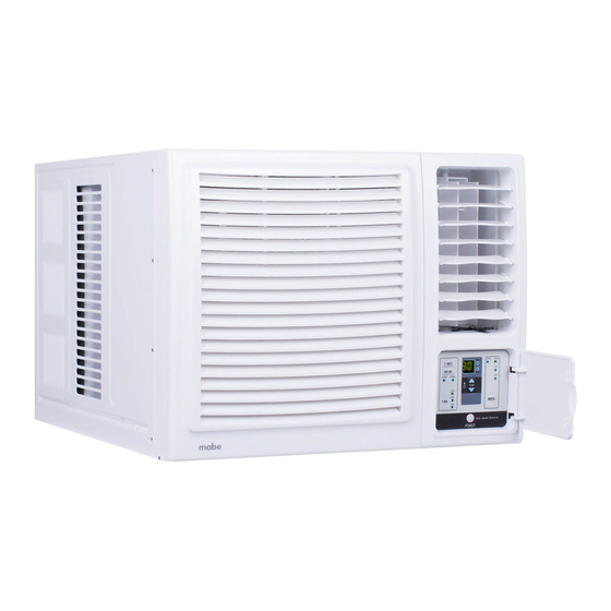
parts of the unit The front panel and cabinet may be slightly different according to the model you acquired, but the functions are the same. The follow- ing illustration is for explanation purpose only, the actual shape of the machine you purchased may be slightly different. Model A Front panel Air outlet grille... - Page 10 accessories Seal (optional) Drain joint (Used on (optional) Drain tray (optional) drain joint) 1 piece 1 piece 1 piece 1 piece Wood screw Rubber Screw (optional) plug 2 pcs (For >18000 BTU/h models only: Used to fasten 1 or 2 pieces the front panel).
-
Page 11: Operation Instructions
operation instructions control panel °C HIGH TEMP COOL MODE Notes: • The illustration of the operation panel is based on a typical model, the functions will be the same for your air conditioner while some difference may exist in appearance. •... - Page 12 Power Press the POWER keypad to turn the unit on/off. Mode Press the MODE keypad to select the appropriate operating mode. The mode selection will alternate between COOL, FAN and DRY. The indicator light next to the "MODE" option will illuminate, identify- ing the mode selected.
- Page 13 TIMER OFF for cooling and fan operation • On cool mode, press the TIMER button for 2 seconds, the TIMER OFF light illuminates and the cool mode light flashes. This indicates that the Auto Stop program for cooling operation is initiated. Press the MODE button, the fan mode light flashes, it indicates that the Auto Stop program for fan operation is initiated.
- Page 14 Ed: Indicates frosting protection. Turn off the unit and restart it to return to normal operation. EI: Indicates the need to check the filter after 720 hours of fan op- eration. Turn off the unit, disconnect/unplug from the power supply. Clean the filter, then restore the power.
- Page 15 When the command is received, the appropriate function will be dis- played (temporarily) in the LED display window and the indicator light corresponding to the selected mode will illuminate in the main control panel. Note: The LED display will default to show the ambient room tem- perature within 10 seconds of all program commands.
- Page 16 SLEEP (on some models) In the Cooling mode, the cooling temperature set point will increase 1 °C per hour after the SLEEP mode is selected. Two hours later, the set point will continue at this temperature and the fan motor will remain on LOW speed.
- Page 17 cleaning the cabinet • Be sure to unplug the air conditioner to prevent shock or fire haz- ard. The cabinet and front may be dusted with an oil-free cloth or washed with a cloth dampened in a solution of warm water and mild liquid dishwashing detergent.
- Page 18 2. Back drainage. Connect drain hose to the back drainage hole. It will slightly affect cooling performance, but will reduce the noise caused by spraying the condensed water. 3. Non-drainage. Block the drain hole(s) using the rubber plug(s). The condensed water will be sprayed to condenser, and will im- prove the cooling performance.
-
Page 19: Installation Instructions
Notes: • If you choose non-drainage when cooling, both the bottom and back drain holes of the unit should be blocked using rubber plugs. When you choose non-drainage, the air conditioner will be perfect cooling efficiency, but big noise may be caused when spraying the condensed with water. - Page 20 CAUTION: All side louvers of the cabinet must remain ex- posed to the outside of the structure. installation of housing Step 1. Remove the air conditioner from its packaging, remove fix- ing screws and slide the air conditioner out of its housing (refer to installation steps).
- Page 21 installation of the unit into the housing 1. Slide the unit into the housing until it rests firmly against the rear of the housing. Care is required to make sure the foam sealing strips on the housing remain in position. 2.
- Page 22 installation sequence Step 1. Remove the front panel and the air filter 1. Hold the slot under the front panel, then uplift it outwards, and remove the front panel (See Fig. 1). 2. Pinch the handle under the air filter and make the air filter arched, remove it from the slot from underside to upside (See Fig.
- Page 23 Wall Cabinet Support bracket Screws Fig. 5 Fig. 6 Fig. 7 Step 3. Installation 1. Grasp the handle on the chassis and carefully slide the air condi- tioner out of the cabinet (See Fig. 5). 2. Remove shipping pad from around compressor before operation and make sure the discharge points to the drain pan are aligned before the chassis is pushed into the cabinet (See Fig.
-
Page 24: Troubleshooting Tips
troubleshooting tips Save time and money! Review the chart below first and you may not need to call for service. normal operation • You may hear a pinging noise caused by water being picked up and thrown against the condenser on rainy days or when the hu- midity is high. - Page 25 Problem Possible cause What to do Air conditioner Air flow is restricted • Make sure there are no does not cool as curtains, blinds, or furni- it should. ture blocking the front of the air conditioner. The air filter is dirty. •...
-
Page 26: Specifications
specifications Unit dimensions Model Body dimensions (WxHxD) 445x320x415 mm 5000~6000 BTU/h 450x346x535 mm 450x346x535 mm 7000~9000 BTU/h 450x346x585 mm 560x400x640 mm 9000~12000 BTU/h 600x380x560 mm 15000~16000 BTU/h 660x434x620 mm 660x428x680 mm 15000~24000 BTU/h 660x428x780 mm Note: "D" value is for reference only. Minimum nominal cross-section area of conductors Rated current of appliance (A) Nominal cross-section area...
Need help?
Do you have a question about the MEE09VV and is the answer not in the manual?
Questions and answers