Table of Contents
Advertisement
Quick Links
Advertisement
Table of Contents

Related Manuals for Advanced Wireless Communications AWR-DM7700


Summary of Contents for Advanced Wireless Communications AWR-DM7700
- Page 1 User Manual AWR-DM7700 DMR Digital Two-Way Radio...
- Page 2 AWR-DM7700 delivers the latest technology, has the most stable components, and has the most advanced production technology. The AWR-DM7700 mobile radio will provide you with the reliable performance and high quality you demand. This manual should be read to ensure that the user understands the operation of the AWR-DM7700.
- Page 3 RF exposure can be accomplished using labels, or by education and training through appropriate means such as information and instructions in user manuals or safety booklets. Your Advanced Wireless Communications’ two-way radio or repeater has an RF exposure information label on the device. The training material below includes useful information about RF exposure and helpful instructions.
- Page 4 Advanced Wireless Communications Radio Quality Warranty and Liability The warranty range and limitation Advanced Wireless Communications (AWC) is committed to quality and stands behind its products. AWC will, during the warranty period specified for each product, repair or replace components that fail as a result of poor workmanship or materials.
-
Page 5: Table Of Contents
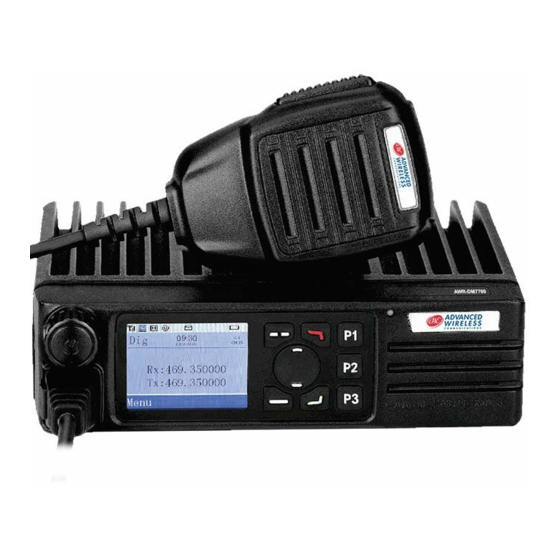
CONTENTS Unpacking and device check .............. 1 Packing list ..................1 Product images................... 1 Front panel ..................1 Front panel functions ..............1 Back panel ..................2 Programmable key functions .............. 2 Installation ..................3 Installation kit .................. 3 Installation steps ................4 Status indication ................. -
Page 6: Unpacking And Device Check
If any item has been lost or damaged, please submit a claim with the carrier or deliverer. Items Quantity AWR-DM7700 Mobile Radio Microphone Microphone Hanger w/Hardware Power Cable w/Fuse... -
Page 7: Back Panel
Back Panel Programmable Key Functions There are four programmable soft keys, P1, P2, P3, and Call. The following table shows the programmable functions available. Each key can be programmed for a short and long press function as noted in the programming software. Key Parameter Function Application Power Switch... -
Page 8: Installation
Installation Before installing the mobile radio, please read the following precautions carefully. These precautions are applicable to both vehicular or fixed station installations. Precautions • This mobile only operates off a 13.6VDC, ±15% negative ground power system. Please verify the power system and its operational capability before installation. -
Page 9: Installation Steps
Preparation Steps Install the u-bracket to the desired position Put the platform on the u-frame and secure it with screws Connect the speaker microphone... -
Page 10: Status Indication
Status Indication LCD Icon Icon Name Icon Status Description Emergency Alarm Radio is in an emergency alarm state or has received an emergency alarm Transmitting Indicator The radio is transmitting Signal Indicator Receiving signal No signal Transmit Power Current channel power is low-power Current channel power is high-power Speaker Squelch and speaker turned on... -
Page 11: Product Operation
Product Operation User Mode Power on / Power off Press the power button and the prompt tone ‘Du’ should be heard, the green light will flash, the mobile radio is turned on. A long press of the power button turns off the mobile radio. Volume Control Rotate the [Power/Volume] knob to adjust the volume, clockwise to increase the volume, and counterclockwise to decrease the volume. - Page 12 Product Operation (continued) Note: Other users must share the same programming to be able to receive a call from the contact list. Once a user exits the contact list selection, the radio reverts to the channel preset. It does require knowledge of the talk groups and users when using the contact list method.
-
Page 13: Analog Operation
Analog Operation Analog Call – Analog calling has no special calling methods. To make a call on an analog channel, the user selects the channel, presses the PTT button, speaks in the microphone and releases it to listen to the other party’s reply. Call Operation Group Call Digital Transmit: Select a preset digital channel or use the menu to select a group on which to make a call. -
Page 14: Call Operation
Call Operation (continued) Private Call Digital Receive: Upon receiving a private call on a digital channel the radio’s screen will show the following. All Call Digital Transmit: Select the all call preset channel or use the menu to select all call. Press and hold the PTT to send the all call. The screen in transmit will show the following. -
Page 15: Menu
Call Operation (continued) Analog Transmit: Select an analog channel on which to make a call. Press and hold the PTT with the microphone 3 to 5 cm (1 to 2 in.) away from mouth. The screen will show the following. Analog Receive: Upon receiving a call on an analog channel with matched digital signaling, the radio’s screen will show the following. -
Page 16: Contacts
There are sub-menus under each of the categories. Like the menu items, they may or not be available to the end-user based on programming. In most use cases only, a few items will be enabled. To access the Menu, press the menu button. The Up / Down keys are used to navigate to the selected menu item, and a button press will access the available sub-menus. - Page 17 Contact (continued) New Contact Allows entry of new contact ID and alias that may be accessed via the Contact List. When the selection has been created, enter the contact list and select New Contact. Manual Dialing Allows the user to enter the ID of the targeted user from a front panel key to make a call.
- Page 18 Call Record (Digital Only) The Call Record allows the user to view received calls, dialed calls and missed calls. There are additional selections under each of these items. Common Function (Digital / Analog) The Common Function provides the ability to select Scan On/Off and Squelch On/Off.
- Page 19 Service (Digital Only) Service allows access to special supplementary services defined by the DMR standard. They may or may not be activated in programming. They will mainly be used only in supervisor or management radios for transmission. These selectable items are Call Prompt, Remote Monitor, Radio Check, Radio Kill, and Active.
- Page 20 (952) 469-5400 / Toll Free: (800) 475-5852 20809 Kensington Blvd Lakeville, MN 55044-8353 www.AdvancedWireless.com ©2019 Advanced Wireless Communications. All rights reserved. 501107...
Need help?
Do you have a question about the AWR-DM7700 and is the answer not in the manual?
Questions and answers