
Subscribe to Our Youtube Channel
Related Manuals for Grundfos DELTA HCU


Summary of Contents for Grundfos DELTA HCU
- Page 1 GRUNDFOS INSTRUCTIONS GRUNDFOS DELTA HCU 60 Hz North America Installation and operating instructions GRUNDFOS DELTA HCU Installation and operating instructions (all available languages) http://net.grundfos.com/qr/i/92705454...
- Page 3 GRUNDFOS DELTA HCU English (US) Installation and operating instructions ............4...
-
Page 4: Table Of Contents
Control variant ......6 warranty. Grundfos will not be liable for damage or wear to products Identification. -
Page 5: General Information
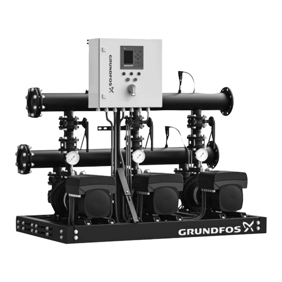
3.1 Product description Installation and operation must comply with local As standard, the GRUNDFOS DELTA HCU pump skid consists of regulations and accepted codes of good practice. two to five identical NBS or NBSE pumps in parallel, installed on a common base with all necessary pipes and control equipment. -
Page 6: Intended Use
100 °C) up to a maximum pressure of 175 psi (12 bar). Blind flange 3.4 Control variant Support bracket for cabinet and VFD The Grundfos DELTA HCU pump skids are divided into two groups Control panel based on the control variant: Grundfos CUE... -
Page 7: Identification
Applies only to systems. Product name Applies only to CR, CRI, CRN, CRE and CRIE pumps. Factory code and production code (year and week) A GSC (Grundfos Standard Configuration) file is a Serial number configuration data file. Mains supply Maximum operating pressure [psi] Temperature range of liquid Max. - Page 8 3.5.3 Type key Example: Delta HCU-E4NBSE 050-090-UL-U-V-I8-ABCD Code Description Designation DELTA HCU Product name E: Multi-E control, with E motor I: MPC, with E motor or CUE System type X: Customized system type Number of main 2, 3, 4 etc.
-
Page 9: Receiving The Product
The base frame contains some holes in the four corners for installing the lifting equipment. See the figure below. 4.1 Transporting the product Depending on the size, GRUNDFOS DELTA HCU is placed in a wooden crate designed for forklift trucks or similar transportation equipment. -
Page 10: Mechanical Installation
6. Mechanical installation To optimize the operation and minimize the noise and vibration, it may be necessary to consider vibration damping of the system. WARNING Noise and vibration are generated by the motor and pump rotations, Body injury and flow in the pipes and fittings. The effect on the environment is Death or serious personal injury subjective and depends on the correct installation and the state of ‐... -
Page 11: Foundation
6.2 Foundation The minimum height of the foundation, h , is calculated by the equation below: We recommend that you install the system on a flat plane and rigid W system × 1 . 5 concrete foundation which is heavy enough to provide permanent h f = support for the entire system. -
Page 12: Starting Up The Product
9. As the pumps stop, check the pump rotation. Repeat this step if • Make sure that the DELTA HCU controls and the pumps are necessary. suitable for the electricity supply on which they will be used. See the section on Technical data. - Page 13 10. When the pumps are vented and checked for correct rotation, the system is now ready for operation. As the isolation valves on the outlet side are still closed, partially open each outlet isolation valve to allow water to enter into the outlet pipe. Continue the process of filling the outlet pipe until the outlet piping pressure is approximately at the desired setpoint pressure of the system.
-
Page 14: Cu 352 Control Panel
9. CU 352 control panel 9.1 Buttons and indicator lights The buttons on CU 352 control panel are active when they are on. The control panel in the front cover of the controller features a display, a number of buttons and two indicator lights. The control 9.1.1 Arrow to the right (2) panel enables manual setting and monitoring of the performance of Press [>] to go to the next menu in the menu structure. -
Page 15: Display
9.2 Display 10. Functions 10.1 Overview of functions Display and display number Status (1) This menu shows alarms, status of the system and a graph of logged data. Note: No settings can be made in this menu. Actual alarms (3.1) System (1.2) Operating mode (1.2.1) Setpoint (1.2.2) -
Page 16: Description Of Functions
Display and display number Display and display number PI controller (4.1.1) Max. pressure (4.4.3) Alternative setpoints (4.1.2) External fault (4.4.4) • Alternative setpoints 2-7 (4.1.2.1 - 4.1.2.7) Limit 1 exceeded (4.4.5 - 4.4.6) External setpoint influence (4.1.3) Pumps outside duty range (4.4.7) •... -
Page 17: Status (1)
10.3 Status (1) If the fault is related to one of the pumps, one of the symbols is also shown in front of the status line (D) of the pump in question. This display is shown when the power is switched on, and it At the same time, the pump status indicator (E) changes colour to appears if the buttons of the control panel remain untouched for 15 either yellow or red as described in the table below. - Page 18 10.3.2 System (1.2) 10.3.3 Operating mode (1.2.1) System Operating mode Description Description The display shows the operational state of the system. Go to The display shows the operating mode of the system and from subdisplays for further details. where it is controlled. The display allows you to open the displays below: Operating modes The system has six operating modes:...
- Page 19 Control source 10.3.5 Setpoint influence (1.2.3) You can set the system to remote control via an external bus (option). In this case, you must set a setpoint and an operating mode via the bus. In the menu Settings, you can select whether CU 352 or the external bus is to be the control source.
- Page 20 10.3.6 Measured values (1.2.4) 10.3.7 Analog inputs (1.2.5) Measured values Analog inputs Description Description The display gives a general status of all measured and calculated The display shows an overview of the analog inputs and the parameters. In MPC-E systems with a flowmeter, the specific measured values of each input.
- Page 21 10.3.8 Log graph (1.2.6) 10.3.9 Battery status (1.2.7) Battery status Log graph Description Description The display shows the status of the backup battery, if installed. The display shows logged data stored in the controller. Select log values in the display Log values (4.4.9). Various values can be shown, and the time scale can be changed.
-
Page 22: Operation (2)
10.3.10 Pump 1-6, Pilot pump (1.3 - 1.10) 10.4 Operation (2) In this menu, you can set the basic parameters, such as setpoint, operating mode, control mode and individual pump control. 10.4.1 Operation (2) Pump 1 Description The display shows the operational state of the individual pumps. Operation The displays for the pilot pump are only shown if such Description... - Page 23 Further settings 10.4.2 System operating mode (2.1.1) • Operation > Further settings. Select one of the settings below: • System operating mode, see section System operating mode (2.1.1). • Control mode, see section Control mode (2.1.2). • Alternative setpoints, see section Alternative setpoints (2.1.3). •...
- Page 24 10.4.3 Control mode (2.1.2) Set the setpoint. See sections Operation (2) and Alternative setpoints (2.1.3). Open loop In open-loop control mode, the pumps run at a fixed speed. The pump speed is calculated from the performance set by the user (0-100 %).
- Page 25 • Select: Open loop. Pos. Description 1. Press × 2. Flow rate [m 2. Select: Stop Input [%] from external controller 3. Set to 100 %: Set setpoint 1, open loop. Flow rate 4. Settings > Primary controller > External setpoint influence > Pump 1-4 Go to setting of analog input.
- Page 26 10.4.4 Alternative setpoints (2.1.3) 10.4.5 Individual pump control (2.1.4) Individual pump control Alternative setpoints Description Description You can change the operating mode from automatic operation to In addition to the primary setpoint 1, shown in display 2 in menu one of the manual operating modes. Operation, you can set six alternative setpoints for closed-loop control mode.
- Page 27 10.4.6 Pump 1-6 (2.1.4.1 - 2.1.4.6) 10.4.7 Operation, pilot pump (2.1.4.7) Pump 1-6 Operation, pilot pump Description Description The display is shown for the individual pumps and it allows you to The display is only shown in systems that have been configured set an operating mode.
-
Page 28: Alarm (3)
10.5 Alarm (3) This menu gives an overview of alarms and warnings. You can reset alarms. 10.5.1 Alarm status (3) Manual/ automatic External fault Manual/ Stop automatic Dissimilar sensor Automatic signals Fault, primary Stop Automatic sensor Fault, sensor Automatic Communication Automatic fault Phase failure... - Page 29 10.5.2 Actual alarms (3.1) 10.5.3 Alarm log (3.2) The alarm log can store up to 24 warnings and alarms. Actual alarms Alarm log Description The submenu in the display Alarm shows the following: Description The display shows warnings and alarms. •...
-
Page 30: Settings (4)
10.5.4 Service contact information (3.3) 10.6 Settings (4) Service contact information Settings Description In the Settings menu, you can set the following functions: The display shows the contact information of the installer if entered • Primary controller during commissioning. PI controller, Alternative setpoints, External setpoint influence, Primary sensor, Secondary sensor, Clock program, Proportional pressure, S-system configuration, Setpoint ramp. - Page 31 10.6.1 Primary controller (4.1) 10.6.2 PI controller (4.1.1) Primary controller PI controller Description Description In the menu, you can set the functions related to the primary The system includes a standard PI controller which ensures that the controller. It is only necessary to make settings in this menu if the pressure is stable and corresponds to the setpoint.
- Page 32 10.6.3 Alternative setpoints (4.1.2) System/application Heating Cooling [seconds] system system Δp L1 < 5 m: 1 L [m] L1 > 5 m: 3 L1 > 10 m: 5 Δp Alternative setpoints Description The function allows you to select up to six setpoints (2 to 7) as alternatives to the primary setpoint (1).
- Page 33 10.6.4 Alternative setpoints 2-7 (4.1.2.1 - 4.1.2.7) 10.6.5 External setpoint influence (4.1.3) Alternative setpoints 2-7 External setpoint influence For each alternative setpoint, select the digital input to activate the Description setpoint. The function allows you to adapt the setpoint by letting measuring You can set a setpoint for closed loop and for open loop.
- Page 34 Setting via the control panel 10.6.6 Setting of influence function (4.1.3.2) • Settings > Primary controller > External setpoint influence > Input value to be influenced by. A list of available parameters appears. 1. Select the parameter which is to influence the setpoint. 2.
- Page 35 4. Set as a percentage: Reduce setpoint to (Point 1). The primary parameter is the outlet pressure. The sensor is connected to AI1 (CU 352). Other primary parameters can be 5. Repeat steps 2 to 4 for all desired parameters. selected in the startup wizard.
- Page 36 10.6.9 Clock program (4.1.6) 1. Enable the function. 2. Select and enable one of the ten events. 3. Select: Normal or Stop. Skip step 4 if you select Stop. 4. Set: Setpoint, closed loop. 5. Set: Time, Hours, Minutes. 6. Select the day of week on which the settings are to be activated. 7.
- Page 37 10.6.11 S-system configuration (4.1.8) Proportional pressure Pos. Description Pressure at zero flow. Starting point of proportional- pressure control (influence at zero flow = x % of setpoint) Qpmax Setpoint The function has these purposes: • to compensate for pressure losses •...
- Page 38 10.6.12 Setpoint ramp (4.1.9) 10.6.13 Pump cascade control (4.2) Pump cascade control Setpoint ramp In the menu, you can set the functions connected to pump cascade Description control. When the function is enabled, setpoint changes are affected by the The following menus can be selected: setpoint ramp, and the setpoint changes gradually over a period of time.
- Page 39 10.6.14 Min. time between start/stop (4.2.1) 10.6.15 Max. number of starts/hour (4.2.1) Min. time between start/stop Max. number of starts/hour Description Description The function ensures a delay between the starting and stopping of The function limits the number of pump starts and stops per hour for one pump and the starting and stopping of another pump.
- Page 40 10.6.16 Standby pumps (4.2.3) 10.6.17 Forced pump changeover (4.2.4) Standby pumps Forced pump changeover Description Description The function allows you to limit the maximum performance of the The function ensures that the pumps run for the same number of system, by selecting one or more pumps as standby pumps. operating hours.
- Page 41 10.6.18 Pump test run (4.2.5) 10.6.19 Pump stop attempt (4.2.7) Pump test run Pump stop attempt Description Description The function is primarily used in situations where the forced pump The function allows you to set automatic stop attempts of a pump changeover is disabled, and/or if the system is set to operating when several pumps are running.
- Page 42 10.6.20 Pump start and stop speed (4.2.8) Setting via the control panel Description • Settings > Pump cascade control > Pump start and stop speed. The function controls the starting and stopping of pumps. There are two options: • Select: Use fixed speed. 1.
- Page 43 10.6.22 Compensation for pump start-up time (4.2.10) 10.6.23 Secondary functions (4.3) Compensation for pump start-up time Secondary functions Description Description The function is used for MPC-F systems only. In the display, you can set functions that are secondary in relation to the normal operation of the system.
- Page 44 For further information, see the document below. The document is The description of the stop function applies to all systems with also available on Grundfos Product Center. variable-speed pumps. MPC-S systems will have on/off control of all pumps as described in section Overview of control variants.
- Page 45 Setting range Rule of thumb: Speed reduction = 2 x delta pressure for Start/stop band: 5-30 % gradient. 2-50 % of the rated flow rate (Q ) of one of the pumps. (It can only be set if direct Minimum flow rate: Example 1: Increasing the stop limit, Qmin (high flow limit) flow measurement by means of flowmeter •...
- Page 46 System with flow switch 1. Set: Stop limit. Make the following additional settings: 1. Select: Go to setting of digital input. Display Digital inputs As standard, there is a 10-seconds detection hysteresis. (4.3.7) appears. 2. Select the digital input where the flow switch is connected. Factory settings 3.
- Page 47 6. Pressure band cut-in: Set the pressure band in percentage of the setpoint. The pressure band is used for cut-in or cut-out of pumps. • Main pumps cut-out when the pilot pump ramps up to a stable setpoint "+ or and" pressure band outlet pressure •...
- Page 48 10.6.27 Emergency run (4.3.5) 10.6.28 Digital inputs (4.3.7) Digital inputs Emergency run Description Description In the menu, you can set the digital inputs of CU 352. Each input, The function is used in booster applications. When this function has except DI1, can be activated and related to a certain function. been enabled, the pumps will keep running regardless of warnings or alarms.
- Page 49 10.6.29 Functions of digital inputs (4.3.7.1) Factory settings Digital input Function External start/stop. Open contact = stop. DI1 (CU 352) [10] Note: Input No 1 cannot be changed. Monitoring of water shortage (dry-running DI2 (CU 352) [12] protection). Open contact = water shortage (if the system is supplied with this option).
- Page 50 10.6.31 Analog inputs (4.3.8.1 - 4.3.8.7) 10.6.32 Analog inputs and measured value (4.3.8.1.1 - 4.3.8.7.1) Analog inputs Analog inputs and measured value Description Description A function can be related to the individual analog inputs. In the menu, you can set Analog inputs. Each display is divided into three parts: Setting range •...
- Page 51 1. Select: Analog inputs. 10.6.34 Function of digital outputs (4.3.9.1 - 4.3.9.16) 2. Select: Measured input value. Display 4.3.8.1.1 appears. 3. Select input. 4. Press . 5. Set the minimum and maximum sensor value. 10.6.33 Digital outputs (4.3.9) Function of digital outputs Description A function can be related to the individual outputs.
- Page 52 10.6.35 Analog outputs (4.3.10) 10.6.36 Output signal (4.3.10.1 - 4.3.10.3) Analog outputs Output signal Description This display only appears if an IO 351B module is You can select the parameters below. installed. Setting range • 0-100 % signal Description • Flow rate 1-6 CU 352 does not have analog outputs as standard, but the system •...
- Page 53 1. Select analog output and range. 10.6.38 Min., max. and user-defined duty (4.3.14) 2. Select: Parameter. Display 4.3.10.2 appears. 3. Select output. 4. Press . 5. Set: Signal range. 10.6.37 Counter inputs (4.3.11) Min., max. and user-defined duty Description The function allows you to let the pumps run in open loop at a set performance.
- Page 54 10.6.39 Min. duty (4.3.14.1) 10.6.40 Max. duty (4.3.14.2) Min. duty Max. duty Description Description In all systems, apart from MPC-S systems, minimum duty is only The function allows you to set a number of pumps to run at possible for variable-speed pumps. In MPC-S systems, you can maximum performance when the function is enabled.
- Page 55 Read the data using the pump performance curves which can be found in Grundfos Product Center at www.grundfos.com. If Grundfos Product Center is not accessible, try to bring a pump Number of pumps in operation during user-defined duty: into the three duty points: •...
- Page 56 Grundfos Product Center at www.grundfos.com. See the examples below. - Power, Q0, 100 % speed If you cannot access Grundfos Product Center, try bringing a pump - Power, Q0, 50 % speed into the three duty points: - Rated power Pnom.
- Page 57 Read the power values in displays 1.3 to 1.8, depending on the pump. See section Pump 1-6, Pilot pump (1.3 - 1.10). Reading of Qnom, Hnom, Hmax and Qmax (Grundfos Product Center) Reading of power, Q0, 50 % speed (Grundfos Product Center) Pos. Description Pos.
- Page 58 Related information 10.6.46 Fixed inlet pressure (4.3.22) 10.3.10 Pump 1-6, Pilot pump (1.3 - 1.10) 10.6.45 Control source (4.3.20) Fixed inlet pressure Description Control source The function is only used when no inlet-pressure sensor is fitted in the system and the inlet pressure is fixed and known. Description If the system has a fixed inlet pressure, you can enter it in the The system can be remote-controlled via an external bus...
- Page 59 10.6.47 Flow estimation (4.3.23) 10.6.48 Reduced operation (4.3.24) Flow estimation Reduced operation Description Description As described in section Pump curve data (4.3.19), CU 352 can The function allows you to limit the number of pumps in operation, optimise operation according to performance curves and motor or for MPC-E systems, to limit power consumption.
- Page 60 10.6.49 Multisensor settings (4.3.25) 10.6.50 Multisensor settings (4.3.25.1) Multisensor settings Multisensor settings Description Each Multisensor needs to be defined in order for the function to Description work correctly. The function is designed for controlling up to six different zones in a HVAC system with a defined differential-pressure band.
- Page 61 10.6.51 Multisensor 1-6 (4.3.25.1.1) 10.6.52 Differential sensor (4.3.27) Differential sensor Multisensor 1-6 Description Up to four differential sensors can be configured for input and Description output values. Each Multisensor needs to be defined in order for the function to work correctly. Example Setting range Differential sensor 2...
- Page 62 10.6.53 Differential sensor (4.3.27.1-4) 10.6.54 Customisable measured value type (4.3.28) Customisable measured value type Differential sensor 1-4 Description Description Up to 8 input value types can be customized in regard to name and Customising the differential sensors. physical quantity. Setting range •...
- Page 63 10.6.55 Customisable measured value type (4.3.28.1-8) 10.6.56 Monitoring functions (4.4) Customisable measured value type Monitoring functions Description Description The system has a series of functions that constantly monitor the • Name: Configure the name for the measured value. operation of the system. •...
- Page 64 10.6.57 Dry-running protection (4.4.1) 10.6.58 Pressure/level switch (4.4.1.1) Dry-running protection Pressure/level switch Description Description Dry-running protection is one of the most important monitoring The function is primarily used in booster applications. Dry-running functions, as the bearings and the shaft seal may be damaged if the protection can take place by means of a pressure switch on the inlet pumps run dry.
- Page 65 10.6.59 Measurement, inlet pressure (4.4.1.2) 10.6.60 Measurement, tank level (4.4.1.3) Measurement, inlet pressure Measurement, tank level Description Description Dry-running protection can take place by means of a pressure Dry-running protection can take place by means of a level transmitter measuring the inlet pressure. transmitter measuring the level in a tank on the inlet side.
- Page 66 10.6.61 Min. pressure (4.4.2) 10.6.62 Max. pressure (4.4.3) Min. pressure Max. pressure Description Description The outlet pressure will be monitored if the application is pressure The outlet pressure will be monitored if the application is pressure boosting. In all other applications, the system pressure will be boosting.
- Page 67 10.6.63 External fault (4.4.4) 10.6.64 Limit 1 exceeded (4.4.5 - 4.4.6) External fault Limit 1 exceeded Description Description The function is used when CU 352 is to be able to receive a fault With the function, CU 352 can monitor set limits of analog values. It signal from an external contact.
- Page 68 1. Select analog input. 10.6.65 Pumps outside duty range (4.4.7) 2. Select: Input value to be monitored. Display 4.3.8.1.1 appears. 3. Select input. 4. Press 5. Set the minimum and maximum sensor value. 6. Press × 2. 7. Select: Input value to be monitored. 8.
- Page 69 10.6.66 Pressure relief (4.4.8) 1. Select digital output. 2. Select: Pressure relief valve. 3. Press × 2. 4. Select: Pressure to be monitored • Select: Outlet pressure, System pressure or External pressure. 5. Press 6. Select and set: • Valve opening pressure •...
- Page 70 10.6.68 Fault, feedback sensor (4.4.10) 10.6.69 Non-return valve (4.4.11) Non-return valve Fault, feedback sensor Description Description The function enables CU 352 to detect if a Non-return valve is You can set how the system is to react if the primary sensor fails. leaking or faulty.
- Page 71 10.6.70 Controlled output 1-2 (4.4.13-4.4.14) 1. Low: If the level drops below the Low limit, a warning occurs and activates the digital output Controlled output, Low and simultaneously deactivates the digital output Controlled output, if it is not deactivated beforehand. 2.
- Page 72 10.6.71 Functions, CU 352 (4.5) Alarm switches Functions, CU 352 Setting via the control panel • Settings > Monitoring functions > Controlled output 1/ Description Controlled output 2. Make the basic settings of CU 352 in this submenu. 1. Select Alarm type. CU 352 comes with most of these settings, or they are made at 2.
- Page 73 10.6.72 Display language (4.5.1) Factory settings The display language is British English. It can be changed at startup. 10.6.73 Units (4.5.2) Display language Description Here you select the language for the CU 352 display. Units Setting range • English Description •...
- Page 74 Setting via the control panel 10.6.74 Date and time (4.5.3) • Settings > Functions, CU 352 > Units. Set unit standard, measuring parameter and specific unit. See the example below. Date and time Description Example of selection of units You can set date and time as well as how they are to be shown in the display.
- Page 75 The Ethernet security disclaimer must be read and acknowledged before Ethernet can be enabled. See also section Ethernet. If you have forgotten the password(s), contact Grundfos. Setting via the control panel • Settings > Functions, CU 352 > Ethernet.
- Page 76 CU 352 can communicate with external units via an RS-485 interface (option). For further information, see section Data communication. Communication is carried out according to the Grundfos bus protocol, GENIbus, and enables connection to a building management system or another external control system.
- Page 77 10.6.79 Status display menu (4.6) Setting via the control panel • Settings > Status display menu 1. Select display 1, 2 or 3, press [OK]. 2. Define a name for display. 3. Select the value for the display 1, 2 or 3. Factory settings Display 1: PV, Primary sensor Display 2: SP, Actual setpoint...
-
Page 78: Data Communication
CU 352 is equipped with a hardware enabling communication with external units, such as a computer, via an external GENIbus or ethernet connection. Data communication via external GENIbus and ethernet connection Pos. Description Intranet Internet External GENIbus connection Ethernet connection External GENIbus module (option) Grundfos CIU communication interface Third-party gateway Related information 10.6.45 Control source (4.3.20) 10.6.77 GENIbus number (4.5.6) - Page 79 10.7.1 Ethernet Ethernet is the most widely used standard for local networks (LAN). The standardisation of this technology has created some of the easiest and cheapest ways of creating communication between electric units, for instance between computers or between computers and control units. The webserver of CU 352 makes it possible to connect a computer to CU 352 via an ethernet connection.
- Page 80 See examples in the section Data communication. For further information, contact Grundfos. The gateway may be a Grundfos CIU communication interface or a third-party gateway. For further information on CIU, see Grundfos Product Center, or contact Grundfos.
-
Page 81: Servicing The Product
11. Servicing the product For long-term end-of-line service, we recommend that you install a blind or companion flange for safety precautions. DANGER Electric shock Death or serious personal injury 11.1 Maintaining the product ‐ Disconnect the power supply before you start maintaining the product. -
Page 82: Protecting The Product Against Frost
Cut in the main switch. The main switch is defective. • Replace the main switch. The motor protection is • Contact Grundfos. activated. Drain plug (E), priming and venting plug (M) The motor is defective. • Repair or replace the motor. -
Page 83: Pumps Start But Stop Immediately
Connect the power supply. the pump shaft. switched off. CU 352 is defective. • Contact Grundfos. 12.9 Very frequent starts and stops There are very frequent starts and stops. 12.4 Unstable water supply from system The water supply from the system is unstable. -
Page 84: Technical Data
Open-circuit voltage 12 VDC ± 15 % Closed-circuit current 2.6 mA, DC On request, Grundfos offers DELTA HCU pump systems with a liquid temperature higher than 212 °F (100 °C). Inputs for PTC sensors are electrically separated from the Related information other inputs and outputs of the pump system. -
Page 85: Related Documents
This product or parts of it must be disposed of in an environmentally sound way. 1. Use the public or private waste collection service. 2. If this is not possible, contact the nearest Grundfos company or service workshop. See also end-of-life information at www.grundfos.com/product-... - Page 86 2941 Brighton Road Oakville, Ontario L6H 6C9 Tel.: +1-905 829 9533 Fax: +1-905 829 9512 Mexico Bombas GRUNDFOS de México S.A. de C.V. Boulevard TLC No. 15 Parque industrial Stiva Aeropuerto Apodaca, N.L. 66600 Tel.: +52-81-8144 4000 Fax: +52-81-8144 4010...
- Page 87 92705454 06.2023 ECM:1369812 www.grundfos.com...
Need help?
Do you have a question about the DELTA HCU and is the answer not in the manual?
Questions and answers