
Related Manuals for Tek-Trol TEK-BAR 3120B Series


Summary of Contents for Tek-Trol TEK-BAR 3120B Series
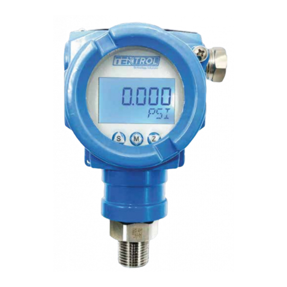
- Page 1 Technology Solutions AR 3120B Smart Gauge Pressure Transmitters Instruction Manual Document Number: IM-3120B www.tek-trol.com...
- Page 2 Crystal Lake, IL 60014 Tel: +1 847 857 6076, +1 847 655 7428 © COPYRIGHT Tek-Trol LLC 2019 No part of this publication may be copied or distributed, transmitted, transcribed, stored in a retrieval system, or translated into any human or computer language, in any form or by any means, electronic, mechanical, manual, or otherwise, or disclosed to third parties without the express written permission.
-
Page 3: Table Of Contents
Table of Contents Table of Contents ..........................1 Safety Instructions ......................3 Intended Use ........................3 Certification ........................3 Safety Instructions from the Manufacturer .................3 Disclaimer ..........................3 Product Liability and Warranty ....................3 Information Concerning the Documentation ................3 Safety Precautions ........................4 Packaging, Transportation, and Storage ................5 .......................... - Page 4 Liquid flow measurement ..................... 17 Air flow measurement......................17 Open container level measurement-single flange level transmitter ........17 Sealed container level measurement-single flange level transmitter ........17 Electrical Connections ....................18 Grounding of Measuring Device ..................18 Power Supply Specifications and Connection ..............19 Cable Protection System ....................
-
Page 5: Safety Instructions
1 Safety Instructions 1.1 Intended Use Tek-Bar 3120B is a Smart Gauge Pressure Transmitter used for pressure, flow, level and density measurement of steam and liquids. The manufacturer is not liable for damage caused by improper or non-designated use. 1.2 Certification Tek-Bar 3120B has approval (Class I Div. -
Page 6: Safety Precautions
Safety Precautions You must read these instructions carefully prior to installing and commissioning the device. These instructions are an important part of the product and must be kept for future reference. Only by observing these instructions, optimum protection of both personnel and the environment, as well as safe and fault-free operation of the device can be ensured. -
Page 7: Packaging, Transportation, And Storage
1.4 Packaging, Transpor n, and Storage This sec on contains informa on regarding packaging, transporta on, and storage. Packaging The original package consists of Tek-Bar 3120B Smart Gauge Pressure Transmi er Accessories (op onal) Documenta on NOTE Unpack and check the contents for damages or signs of rough handling. Report damage to the manufacturer immediately. -
Page 8: Storage
Storage If this product is to be stored for a long period of time before installation, take the following precautions: Store your product in the manufacturer’s original packing used for shipping. Storage location should conform to the following requirements: Free from rain and water Free from vibration and impact shock At room temperature with minimal temperature and humidity variation Before storing a used owmeter remove any uid from the owmeter line... -
Page 9: Product Description
Tek-Bar 3120B. The performance accuracy is up to 0.075% of URL. This high-performance pressure transmitter meticulously designed by Tek-Trol supports HART communication protocol and IP66 waterproof protection. It is well equipped with several features that facilitate easy installation, start-up and minimum maintenance. -
Page 10: Specifications
2.3 Speci c ons General Speci ca ons Parameter Descrip on Pressure Type Gauge Pressure Accuracy ±0.075% F.S. Diaphragm Materials Hastelloy C Stability ±0.2 % URL/5 year Process Connec on ±0.075% F.S. We ed material 316LLS Working Humidity 5 to 100% Output Signal Apply to any posi on. -
Page 11: Power Supply
Power Supply Parameter Descrip Power supply 10.5-55VDC (Hart: 16.5-55VDC) Load resistance 0-2119 for working condi n, 250- 600 for HART protocol Transmission <3281 distance Power consump mW at 24VDC, 20.8 mA Measuring Range Limit for Tek-Bar 3120B Smallest Lower Range Limit Upper Range Limit Nominal Overload... -
Page 12: Model Chart
2.5 Model Chart Tek-Bar 3120B-G Tek-Bar 3120B-G-3-WP-1-HC-1-BA Example Tek-Bar 3120B-G Smart Gauge Pressure Transmi er Series Range Op ons General Purpose NEMA 4X/IP66 Approval Ra ng ½" NPT Male Process Connec ons Diaphragm Seal Hastelloy C Diaphragm Material ½" NPT Female Electrical Connec ons Custom with 5 point... -
Page 13: Installation
3 Installation This section covers instructions on installation and commissioning. Installation of the device must be carried out by trained, qualified specialists authorized to perform such works. CAUTION When removing the instrument from hazardous processes, avoid direct contact with the fluid and the meter All installation must comply with local installation requirements and local electrical code 3.1 Selecting the Installation Location... -
Page 14: Process Connections
Process Connections 3.2.2.1 Straight Thread Connection Picture 1 Picture 2 Picture 1: Ensure that the seal of head face gasket is effective by keeping the length of the pressure transmitter thread longer than the depth of the thread. Picture 2: Ensure that the seal of root gasket is effective by maintaining the length of the pressure transmitter thread shorter than the depth of the thread. -
Page 15: Housing Rotation
Choose gaskets that meet speci ed standards to avoid excessive clamp locking and squeezing gasket. Excessive locking of clamp may damage the sensing diaphragm and cause measuring error. NOTE Engage process connec on with a minimum of 7 thread connec ons and ghten the housing rota on set screw to prevent it from rota ng Housing Rota on To ensure the visibility of LCD display... -
Page 16: Conduit Installation
Conduit Installa Improper sealing of connec ons may damage the transmi er due to excess moisture accumula on. Mount the transmi er with electrical housing posi oned downward so that the excess of moisture is condensed and drained out from the casing. Secondly, install wiring with a drip loop and ensure the bo om of the drip loop is mounted lower than the conduit connec ns or the transmi er housing to avoid moisture accumula on... -
Page 17: Gas Flow Measurement
Gas Measurement Place the taps in the top or side of the line Mount the transmi er beside or above the taps so liquid will drain into the process line Steam Measurement Place taps to the side of the line Mount the transmi er below the taps to ensure that the impulse piping stays with condensate In steam service above 250°F (121°C),... -
Page 18: Field Adjustment
3.4 Field Adjustment Perform field adjustments only after installing the transmitter at its final work location otherwise the set parameters may drift due to jerks while transporting or handling. Zero Point Adjustment For sensor zero trim, ensure that the vessel is empty and there is no input medium pressure on the diaphragm. -
Page 19: Steam Flow Measurement
Differential pressure transmitters are commonly used for micro pressure measurement of hydrostatic pressures such as filter and equipment leakage tests for improving accuracy. Steam flow measurement For steam flow measurement, up-tilt the guiding pressure tube by 45°. Ensure that transmitter installation location is at lower level than that of the process pipeline. Pre- inject cooling liquid into the guiding pressure tube. -
Page 20: Electrical Connections
4 Electrical Connections This section covers the all electrical connection requirement. Electrical connection of the device must be carried out by trained, qualified specialists authorized to perform such work by the installation site. WARNING Connect all electrical cables when the power is switched off. If the device does not have switch-off elements, then, overcurrent protection devices, lightning protection and/or energy isolating devices must be provided by the customer. -
Page 21: Power Supply Specifications And Connection
4.2 Power Supply Specifications and Connection Use independent linear direct current power supply for pressure transmitter. Large resistive load results in high pressure drop. Therefore, it is recommended to consider the resistance across the signal cable, display meter and other equipment to ensure sufficient voltage is provided to the pressure transmitter for its normal operation. -
Page 22: Cable Protection System
Power Supply Connections 4.3 Cable Protection System Apply following cable protection measures to protect the connecting cables from various factors that affect negatively on the cable lifetime. Standard Protection System To avoid liquid flowing along with the cable into the terminal box, configure a U-shaped ring between pull box and pressure transmitter as shown in the figure below. -
Page 23: Explosion-Proof Tube Protection System
Explosion-proof Tube Protection System If the transmitter is situated in dangerous area, use a high quality metallic explosion- proof tube as a casing for the cable connecting the transmitter to the terminal box. Connection to the HART Handheld Communicator . Transmitter operates on 11.9 45 VDC. -
Page 24: Operation
5 Operation This section covers operation techniques and guidelines along with the configuration and calibration. NOTE Calibrate the instrument according the instructions given in this section, otherwise it could lead to measurement error. 5.1 Local Operation and Display Tek-Bar 3120B is available with the optional LCD display. The local display enables user to read important parameters directly at the measuring point and configure the device using the function matrix. -
Page 25: Key Operation
Z: Enter the se ng op ons S: Modify the parameter value M: Con m the set value and enter the next menu The same keys are used in combina to perform several advanced func Key Opera Consider the factory se ng for pressure measurement is set as follows: Pressure range: -10 to 100 kPa;... - Page 26 Measuring Smart Interface 5.457 Confirm and enter the next menu Enter settings Modify parameters Set parameters Display modified Current parameters parameters DISP DISP DISP Confirm and enter the next menu Current parameters Set parameters Display modified Enter settings Modify parameters parameters Confirm and enter the next menu Confirm and output calibration current...
- Page 27 (Only suitable for processing units: mm, m, m/s ) Current Enter settings Modify parameters parameters parameters 1.0001 1.0000 1.0000 DENSITY DENSITY DENSITY Current Display selected Modify parameters parameters Enter settings parameters parameters 1.0001 1.0000 1.0000 HEIGHT HEIGHT m HEIGHT m (Only suitable for processing units: m/s ) Current Display selected...
- Page 28 Parameter Table Parameter Values Display mode Percentage Process variable Current Units Use the keys Z() and S() to change the units mmHg mmH2O mH2O inH2O ftH2O inHg TORR mbar g/cm2 Kg/cm2 Lower and Upper -19999-99999 range Damping time 0 ~ 100 s Output signal type Square root LINER...
-
Page 29: Handheld Communicator
Cutting value 0-99.999 Pressure type GAUGE Gauge, differential ABSOLUTE Absolute pressure 5.4 Handheld Communicator If custom display is not available, then configure transmitter parameter using communicator. Decimal point position, Upper range value, Lower range value, Engineering units are configured. See the below flow chart. -
Page 30: Maintenance
6 Maintenance This section covers maintenance techniques and guidelines. WARNING Explosion can result into a serious injury or death. Do not remove the transmitter cover in explosive environments when the circuit is live. After disconnecting power wait for a minute to allow the circuit and enclosure to cool down before opening. -
Page 31: Depot Repair
Mechanical cleaning of the diaphragm is strictly prohibited. Do not point the nozzles to the diaphragm when cleaning by pressure washer. Depot Repair Execute following steps before sending the device for depot repair: Disconnect the transmitter carefully. Preserve all accessories and cables for reassembling. -
Page 32: Troubleshooting
7 Troubleshooting This section provides troubleshooting techniques for most common operating problems. When device malfunction is suspected despite the absence of any diagnostic messages on the HHT, inspect following points. If measurement signal appears irregular, check whether the process pressure is within the working range, or the abnormality lies in the measuring system, installation environment or pressure transmitter. - Page 33 Power Supply Check the output voltage of the power supply at the transmitter terminals. It should be 11.9 to 45 VDC in spite of loop scale Electronics Module Connect enter Transmitter test mode to isolate module failure. Check the sensor limits ensure calibration...
-
Page 34: Tek-Bar 3120B Smart Gauge Pressure Transmitter Lcd Display Error Codes
7.2 Tek-Bar 3120B Smart Gauge Pressure Transmitter LCD Display error codes Message Description ADJ-U Out of Zero setting value when Zero Adj function using button (upper side) ADJ-L Out of Zero setting value when Zero Adj function using button (lower side) ZERO Initial message in using the Zero button SPAN... - Page 35 Tek-Trol is a fully owned subsidiary of TEKMATION LLC. We o er our customers a comprehensive range of products and solutions for process, power and oil & gas industries. Tek-Trol provides process measurement and control products for Flow, Level, Temperature &...
Need help?
Do you have a question about the TEK-BAR 3120B Series and is the answer not in the manual?
Questions and answers