Table of Contents
Advertisement
Quick Links
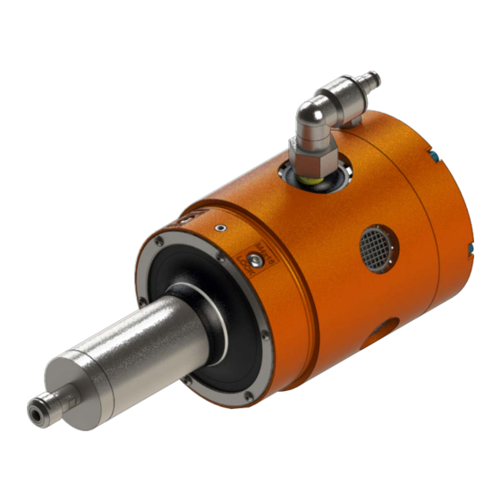
ATI Radially‑Compliant Robotic Deburring Tools
Flexdeburr™ RC‑1000 Series
(Models 9150‑RC‑900‑ER, 9150‑RC‑900‑ER‑E,
9150‑RC‑1040‑ER, and 9150‑RC‑1040‑ER‑E)
Product Manual
US Patent # 6,974,286 B2
Document #: 9610‑50‑1024
Engineered Products for Robotic Productivity
Pinnacle Park • 1031 Goodworth Drive • Apex, NC 27539 • Tel: +1.919.772.0115 • Fax: +1.919.772.8259 • www.ati‑ia.com
Advertisement
Table of Contents
Troubleshooting

Related Manuals for ATI Technologies Flexdeburr RC‑1000 Series


Summary of Contents for ATI Technologies Flexdeburr RC‑1000 Series
- Page 1 ATI Radially‑Compliant Robotic Deburring Tools Flexdeburr™ RC‑1000 Series (Models 9150‑RC‑900‑ER, 9150‑RC‑900‑ER‑E, 9150‑RC‑1040‑ER, and 9150‑RC‑1040‑ER‑E) Product Manual US Patent # 6,974,286 B2 Document #: 9610‑50‑1024 Engineered Products for Robotic Productivity Pinnacle Park • 1031 Goodworth Drive • Apex, NC 27539 • Tel: +1.919.772.0115 • Fax: +1.919.772.8259 • www.ati‑ia.com...
-
Page 2: Foreword
Manual, Flexdeburr, RC‑1000 Series Document #9610‑50‑1024‑05 Foreword CAUTION: This manual describes the function, application, and safety considerations of this product. This manual must be read and understood before any attempt is made to install or operate this product. Failure to do so may result in personnel injury and/or damage to equipment. Information contained in this document is the property of ATI Industrial Automation, Inc (ATI) and shall not be reproduced in whole or in part without prior written approval of ATI. -
Page 3: Table Of Contents
Manual, Flexdeburr, RC‑1000 Series Document #9610‑50‑1024‑04 Table of Contents Foreword ............................2 Glossary ............................5 Safety ............................6 Explanation of Notifications ......................6 General Safety Guidelines ......................7 Safety Precautions ........................7 Product Overview ........................8 Collet System ..........................9 Technical Description ......................... - Page 4 Manual, Flexdeburr, RC‑1000 Series Document #9610‑50‑1024‑04 Preventive Maintenance ......................26 Pneumatics ..........................26 Lubrication ........................... 26 Spindle Boot Inspection ......................26 Bur Inspection ..........................26 Troubleshooting and Service Procedures ................26 Troubleshooting .......................... 27 Service Procedures ........................28 6.2.1 Bur and Collet Replacement .................... 28 6.2.2 Turbine Motor Replacement .....................
-
Page 5: Glossary
Manual, Flexdeburr, RC‑1000 Series Document #9610‑50‑1024‑05 Glossary Definition Term Device for attaching the deburring tool to either a robot flange or a stationary Adapter Plate mounting surface. Device for removing contamination from air supply lines. Typically refers to removal of Air Filter particulates. -
Page 6: Safety
Manual, Flexdeburr, RC‑1000 Series Document #9610‑50‑1024‑05 1. Safety The safety section describes general safety guidelines to be followed with this product, explanations of the notifications found in this manual, and safety precautions that apply to the product. Product specific notifications are imbedded within the sections of this manual (where they apply). -
Page 7: General Safety Guidelines
Manual, Flexdeburr, RC‑1000 Series Document #9610‑50‑1024‑05 1.2 General Safety Guidelines Prior to purchase, installation, and operation of the Flexdeburr product, the customer should first read and understand the operating procedures and information described in this manual. Never use the deburring tool for any purposes, or in any ways, not explicitly described in this manual. -
Page 8: Product Overview
Manual, Flexdeburr, RC‑1000 Series Document #9610‑50‑1024‑05 2. Product Overview The Radially‑Compliant (RC) deburring tool, also known as Flexdeburr, is a robust, high‑speed and lightweight turbine‑driven deburring units for deburring aluminum, plastic, steel, etc. with a robot or CNC machine. The RC deburring tool is especially suited for removal of parting lines and flash from parts. -
Page 9: Collet System
Manual, Flexdeburr, RC‑1000 Series Document #9610‑50‑1024‑05 2.1 Collet System A collet system secures the bur and many collet sizes are available to accommodate a wide variety of applications. All Flexdeburr products utilize removable collets to grip customer supplied cutting tools. Different collet diameters may be substituted to retain numerous cutter shank diameters. -
Page 10: Technical Description
Manual, Flexdeburr, RC‑1000 Series Document #9610‑50‑1024‑05 2.2 Technical Description The technical overview of the product is provided in the following tables and graph. For additional technical specifications, refer to Section 8—Specifications. 2.2.1 Environmental Limitations 2.2.1.1 Operation Table 2.2—Operation Mounted to robot by means of the side mounting pattern or rear adapter flange. -
Page 11: Compliance Unit Performance
Manual, Flexdeburr, RC‑1000 Series Document #9610‑50‑1024‑05 2.2.2 Compliance Unit Performance The graph in Figure 2.2 illustrates the variation of compliance force with applied air pressure in the vertical orientation with the collet pointed toward the ground. Measurements may vary from one product to another and should only be treated as nominal. -
Page 12: Installation
Manual, Flexdeburr, RC‑1000 Series Document #9610‑50‑1024‑05 3. Installation The deburring tool is delivered fully assembled. Optional equipment such as mounting adapter plates, burs, and additional collets will be separate. 3.1 Transportation and Protection during Transportation The RC deburring tool is packaged in a crate designed to secure and protect it during transportation. Always use the crate when transporting the deburring tool in order to minimize the risk of damage. -
Page 13: Side Mounting Installation
Manual, Flexdeburr, RC‑1000 Series Document #9610‑50‑1024‑05 3.5 Side Mounting Installation CAUTION: The length of the fasteners should not interfere with the compliant motion of the turbine motor spindle. Refer to Section 9—Drawings for the maximum fastener length. Do not use fasteners that exceed the maximum length; otherwise, damage will occur. -
Page 14: Axial Mounting Installation
Manual, Flexdeburr, RC‑1000 Series Document #9610‑50‑1024‑05 3.6 Axial Mounting Installation A blank robot adapter plate is also available to allow axial mounting off the rear of the deburring tool housing. This plate may be modified by the system integrator or by the owner/user of the Flexdeburr. ATI can provide custom interface plates and adapters upon request. -
Page 15: Pneumatics
Manual, Flexdeburr, RC‑1000 Series Document #9610‑50‑1024‑05 3.7 Pneumatics Connect the RC deburring tool as shown in Figure 3.3. Figure 3.3—Pneumatic Connections WARNING: All pneumatic fittings and tubing must be capable of withstanding the repetitive motions of the application without failing. The routing of pneumatic lines must minimize the possibility of over stressing, pullout, or kinking the lines. - Page 16 Manual, Flexdeburr, RC‑1000 Series Document #9610‑50‑1024‑05 If the complete work piece can be deburred with equal force, a conventional, manual pressure regulator can be used for compliance. If the burrs to be removed vary from place to place on the work piece, and this variation is repeatable for all work pieces of the same type, it may be necessary to adjust the force using an analog pressure regulator controlled from the robot.
-
Page 17: Operation
Manual, Flexdeburr, RC‑1000 Series Document #9610‑50‑1024‑05 4. Operation These operating instructions are intended to help system integrators program, start up, and complete a robotic deburring cell containing a deburring tool. The system integrator should be familiar with the task of deburring and have extensive knowledge about automation applications that incorporate robots. -
Page 18: Air Quality
Manual, Flexdeburr, RC‑1000 Series Document #9610‑50‑1024‑05 4.2 Normal Operation The following sections describe the normal operating conditions for RC deburring tools. 4.2.1 Air Quality The air supply should be dry, filtered, and free of oil. A coalescing filter with elements rated for 5 micron or better is required. -
Page 19: Flexdeburr Working Environment
Manual, Flexdeburr, RC‑1000 Series Document #9610‑50‑1024‑05 4.3 Flexdeburr Working Environment As described in previous sections, the RC deburring tool should only be used in conjunction with a robot in a secured work cell/chamber. The work cell must be secured by means of barriers to prohibit personnel from entering the cell. A lockable door should be included as a part of the barrier in order to facilitate access to the cell for authorized personnel only. -
Page 20: Locking The Tool To Single Axis Compliance
Manual, Flexdeburr, RC‑1000 Series Document #9610‑50‑1024‑05 4.4 Locking the Tool to Single Axis Compliance The deburring tool can be locked to be compliant in single axis. Included are (4) M4 x 16 button head socket cap screws to lock the tool. CAUTION: Do not use improper length screws for locking the tool axis. -
Page 21: Tool Center Point (Tcp) Position And Programming
Manual, Flexdeburr, RC‑1000 Series Document #9610‑50‑1024‑05 4.5 Tool Center Point (TCP) Position and Programming Figure 4.3 shows the RC deburring tool dimensions. The Flexdeburr provides radial compliance and performs best when the cuts taken are not excessively deep. The deburring tool spindle must never be running while programming the robot. - Page 22 Manual, Flexdeburr, RC‑1000 Series Document #9610‑50‑1024‑05 Figure 4.4—Flexdeburr Pointed Teaching Tool Inside corners represent a complex situation for compliant deburring tools. In general, the bur must not be allowed to simultaneously contact both perpendicular surfaces of an inside corner. The resulting force imbalance in two planes will cause severe tool chatter.
-
Page 23: Cutter Operation And Bur Selection
Manual, Flexdeburr, RC‑1000 Series Document #9610‑50‑1024‑05 4.6 Cutter Operation and Bur Selection The RC deburring tool performs best in “climb milling”, which is when the cutter directions of traverse and rotation are the same. In the case of the RC deburring tools, the bur rotation is clockwise when viewed from above. - Page 24 Manual, Flexdeburr, RC‑1000 Series Document #9610‑50‑1024‑05 ATI can provide guidance in bur selection; however, only experimentation will yield the results desired. The following table is presented to assist in bur selection. This following table is not comprehensive but includes many common bur types and burs recommended for particular applications.
- Page 25 Manual, Flexdeburr, RC‑1000 Series Document #9610‑50‑1024‑05 Table 4.1—Bur Selection Features/Benefits: Materials/Application 9150‑RC‑B‑24645 ‑ Aluminum Cut, 3/8” Bur Diameter, 5/8” Bur Length, 1/4” Shank Easy chip flow‑through positive For greasy aluminum alloys, • • soft non‑ferrous metals and rake angle, rounded base of tooth, thermoplastics convex tooth back No loading of the flutes, not even...
-
Page 26: Preventive Maintenance
Manual, Flexdeburr, RC‑1000 Series Document #9610‑50‑1024‑05 5. Preventive Maintenance The RC deburring tool is designed to provide reliable service for long periods of operation. While simple in design, there are few user serviceable parts in the assembly. The user is encouraged to return the unit to ATI for service. Section 6—Troubleshooting and Service Procedures is provided to assist the user when they chose to service the unit in the field. -
Page 27: Troubleshooting
Manual, Flexdeburr, RC‑1000 Series Document #9610‑50‑1024‑05 6.1 Troubleshooting Deburring process development is an iterative, learning task. The following table is presented to assist in solving deburring problems. Table 6.1—Troubleshooting Symptom Cause Resolution Hard work material Use better grade bur material add coating (TiAlN) Bur wear Too heavy a cut Decrease width of cut/make multiple passes... -
Page 28: Service Procedures
Manual, Flexdeburr, RC‑1000 Series Document #9610‑50‑1024‑05 Table 6.1—Troubleshooting Symptom Cause Resolution Not enough or no Verify drive air regulator is operating at 90 PSI [6.2 Bar] and drive air check for leaks Bur is not secure Properly tighten bur in collet in collet Bur stalls Too much side load... - Page 29 Manual, Flexdeburr, RC‑1000 Series Document #9610‑50‑1024‑05 6. If the collet is being replaced, completely remove the nut and extract the old collet. Insert the new collet and refit the nut leaving it loose. 7. If an identical new bur is replacing a worn one, insert the new bur and measure and adjust the length of its exposed portion according to the measurement taken in step 2.
-
Page 30: Turbine Motor Replacement
Manual, Flexdeburr, RC‑1000 Series Document #9610‑50‑1024‑05 6.2.2 Turbine Motor Replacement If the turbine motor is operated using oil‑laden or dirty air, it will fail and require replacement. Failure of the motor due to contamination in the spindle air is not covered under warranty. The motor may also require replacement after an extended operating life or following a severe collision. - Page 31 Manual, Flexdeburr, RC‑1000 Series Document #9610‑50‑1024‑05 13. Using a 2 mm hex key, loosen the (2) M4 set screws at the bottom of the gimbal ring. 14. Using a 1.3 mm hex key inserted into the side hole of the threaded bushing, turn the bushing in toward the gimbal ring.
- Page 32 Manual, Flexdeburr, RC‑1000 Series Document #9610‑50‑1024‑05 19. Thread M3 fasteners into the pivot pins of the gimbal ring assembly. 20. At the front of the gimbal ring assembly, use a 2.5 mm hex key to loosen the (2) M5 set screws securing the motor pivot pins until they extend out of the front housing about 1/8”.
- Page 33 Manual, Flexdeburr, RC‑1000 Series Document #9610‑50‑1024‑05 25. Install the gimbal ring on the new turbine motor assembly. 26. Insert the pivot pins flush with the gimbal ring to secure it in place. 27. Using a 2.5 mm hex key, install the (2) M5 set screw into the gimbal ring to secure the pivot pins.
- Page 34 Manual, Flexdeburr, RC‑1000 Series Document #9610‑50‑1024‑05 32. Using a 2.5 mm hex key, install the (2) M5 set screws into the front housing assembly to secure the pivot pins. Tighten to 25 in‑lbs (2.82 Nm). 33. Using a 1.3 mm hex key, which is inserted into the side hole of the threaded bushing, turn the bushing out toward the housing until contact and then back in 1/6 of a turn (one through hole).
- Page 35 Manual, Flexdeburr, RC‑1000 Series Document #9610‑50‑1024‑05 43. Assemble the new internal retaining ring and rubber disk to the spindle supply fitting as shown Figure 6.11. 44. Apply non‑hardening thread sealant to the threads of the spindle supply fitting. Do not use thread sealant tape.
-
Page 36: Ring Cylinder Assembly Replacement
Manual, Flexdeburr, RC‑1000 Series Document #9610‑50‑1024‑05 6.2.3 Ring Cylinder Assembly Replacement The compliant motion of the turbine motor spindle is accomplished using an array of pistons (ring cylinder) installed inside the rear housing. After extended operation, this component may need replacing to insure free motion of the pistons. The unit may be replaced as an assembly but its subcomponents are not user serviceable. -
Page 37: Spindle Boot Replacement
Manual, Flexdeburr, RC‑1000 Series Document #9610‑50‑1024‑05 12. Place the M4 screws in the through holes in the ring cylinder body and tighten them slowly and equally using a 3 mm hex key, so they pull the ring cylinder assembly into of the rear housing. Note: Be sure the O‑rings stay seated in their grooves. - Page 38 Manual, Flexdeburr, RC‑1000 Series Document #9610‑50‑1024‑05 8. Apply (1) drop of 10W to 30W oil to each bushing in the gimbal ring. 9. Align the spindle boot and the retaining ring with the holes in the ring cylinder and slide the boot onto the air motor and align the edge of the boot to the edge of the contact sleeve.
-
Page 39: Serviceable Parts
Manual, Flexdeburr, RC‑1000 Series Document #9610‑50‑1024‑05 7. Serviceable Parts For repair and spare parts please contact ATI. Refer to Section 9—Drawings for exploded drawings showing all the user replaceable components of the Flexdeburr. Available accessories, tools, and optional replacement parts are listed in Section 7.1—Accessories Tools, and Optional Replacement Parts. -
Page 40: Specifications
Manual, Flexdeburr, RC‑1000 Series Document #9610‑50‑1024‑05 8. Specifications Table 8.1—9150‑RC‑900‑ER and 9150‑RC‑900‑ER‑E Models Parameter Rating Motor Turbine Motor part number 3490‑0001059‑01 Motor Series 450XHD Idle Speed (RPM) 25,000 (27,500 Max.) Power 900 watts Weight (without Adapters) Approx. 7.6 lbs (3.4 kg) Compensation (Radial) +/‑... - Page 41 Manual, Flexdeburr, RC‑1000 Series Document #9610‑50‑1024‑05 Table 8.2—9150‑RC‑1040‑ER and 9150‑RC‑1040‑ER‑E Models Parameter Rating Motor Turbine Motor part number 3490‑0001058‑01 Motor Series 450XHD Idle Speed (RPM) 40,000 (44,000 Max.) Power 1040 watts Weight (without Adapters) Approx. 7.6 lbs (3.4 kg) Compensation (Radial) +/‑...
-
Page 42: Drawings
Manual, Flexdeburr, RC‑1000 Series Document #9610‑50‑1024‑05 9. Drawings Pinnacle Park • 1031 Goodworth Drive • Apex, NC 27539 • Tel: +1.919.772.0115 • Fax: +1.919.772.8259 • www.ati‑ia.com... - Page 43 Manual, Flexdeburr, RC‑1000 Series Document #9610‑50‑1024‑05 Pinnacle Park • 1031 Goodworth Drive • Apex, NC 27539 • Tel: +1.919.772.0115 • Fax: +1.919.772.8259 • www.ati‑ia.com...
-
Page 44: Terms And Conditions
Manual, Flexdeburr, RC‑1000 Series Document #9610‑50‑1024‑05 10. Terms and Conditions The following Terms and Conditions are a supplement to and include a portion of ATI’s Standard Terms and Conditions, which are on file at ATI and available upon request. ATI warrants the compliant tool product will be free from defects in design, materials, and workmanship for a period of one (1) year from the date of shipment and only when used in compliance with the manufacturer’s specified normal operating conditions. -
Page 45: Motor Life And Service Interval Statement
Manual, Flexdeburr, RC‑1000 Series Document #9610‑50‑1024‑05 10.1 Motor Life and Service Interval Statement The air motors that are used in ATI deburring/finishing tools are subject to wear and have a finite life. Motors that fail, during the warranty period, will be repaired or replaced by ATI as long as there is no evidence of abuse or neglect and that the normal operating practices outlined in this manual have been observed.
Need help?
Do you have a question about the Flexdeburr RC‑1000 Series and is the answer not in the manual?
Questions and answers