Advertisement
GENERAL INFORMATION
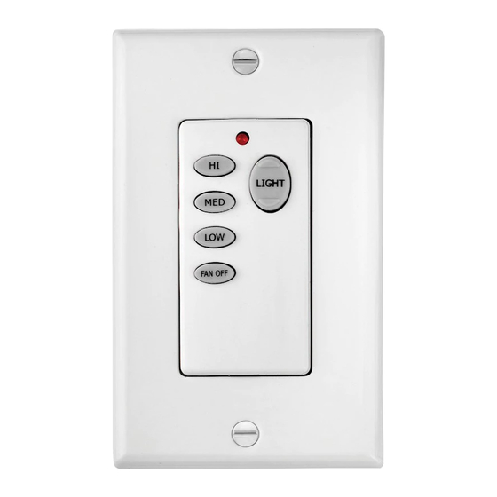
This wall control is designed to separately control your ceiling fan speed and light brightness.
The fan button will control the fan speed. (Hi, Medium, Low)
The light buttons will control the lights, brightness dimmer and off.
The red indicator on the transmitter will light when the button is pressed.
INSTALLATION AND OPERATING INSTRUCTIONS
NOTE: This wall control unit is equipped with 16 code combinations to prevent possible interference from or to other remote units. The
frequency switches on your receiver and transmitter have been preset at the factory. Please recheck to make sure the switches on
transmitter and receiver are set to the same position, any combination of settings will operate the fan as long as the transmitter and
receiver are set to the same position.
1. SETTING THE CODE
This unit has 16 different code combinations. To set the code, perform these steps:
A. Setting the code on the transmitter:
a. Slide the code switches to your choice of up or down position. (Factory setting is all up). Do not use this Position. Use a small screwdriver or a
ballpoint pen to slide firmly up or down (Figure A).
B. Setting the code on the receiver:
a. Slide the code switches to the same positions as set on your transmitter (Figure B).
Fig. A
Transmitter
2. INSTALLING RECEIVER IN THE CEILING FAN
A. Safety precautions:
WARNING: HIGH VOLTAGE! Household electrical power can cause serious injury or death. Disconnect the source of electrical power
to the ceiling fan by removing the fuse or switching off the circuit breaker.
B. Installing receiver in fan.:
a. Remove the ceiling fan canopy from the mounting bracket.
b. Disconnect the existing wiring between the ceiling fan and supply at the electrical junction box.
c. Lay the black antenna wire on top of the receiver, and put the receiver in the mounting bracket. (Fig. C)
d. Make the connections as follows, using the wire nuts supplied: (Fig. D)
CONNECT
Green fan wire...........................................Bare supply wire
Black receiver wire (AC IN L)..................Black supply wire
White receiver wire(AC IN N)..................White supply wire
White receiver wire (TO MOTOR N).......White fan wire
Black receiver wire (TO MOTOR L)........Black fan wire
Blue receiver wire(FOR LIGHT)..............Blue light wire
RECEIVER
Fig. C
ON
HI
LIGHT
MED
LOW
Code switches
ON ECE
FAN OFF
1 2 3 4
TO
WALL CONTROL WITH
SMART CONTROL RECEIVER
INSTALLATION INSTRUCTIONS
READ AND SAVE THESE INSTRUCTIONS
Receiver
Fig. B
AC SUPPLY
WHITE
BLACK
RECEIVER
BLUE
BLACK
WHITE
BARE
Fig. D
3 SPEED FAN & LIGHT
Model: 980030
NOTE: When installing the remote
control, be sure your fan control or
pull chain switch are in the "HIGH
SPEED" position and the light
control or switch is set to "ON".
ON
Code switches
BLUE
BLACK
WHITE
GREEN
Advertisement
Table of Contents

Subscribe to Our Youtube Channel
Related Manuals for Hinkley 980030


Summary of Contents for Hinkley 980030
- Page 1 3 SPEED FAN & LIGHT WALL CONTROL WITH SMART CONTROL RECEIVER INSTALLATION INSTRUCTIONS Model: 980030 READ AND SAVE THESE INSTRUCTIONS GENERAL INFORMATION NOTE: When installing the remote control, be sure your fan control or This wall control is designed to separately control your ceiling fan speed and light brightness.
- Page 2 Code set at exact same position in both transmitter and receiver? For Warranty Information please visit B. Won't operate at distance: www.hinkley.com If transmitter operates the fan and the light kit when up close, but not a 30 feet away, try placing the black antenna wire higher; up through the...
Need help?
Do you have a question about the 980030 and is the answer not in the manual?
Questions and answers