Table of Contents
Advertisement
Advertisement
Table of Contents
Troubleshooting

Related Manuals for Mars Comfort-Aire Century HE Series


Summary of Contents for Mars Comfort-Aire Century HE Series
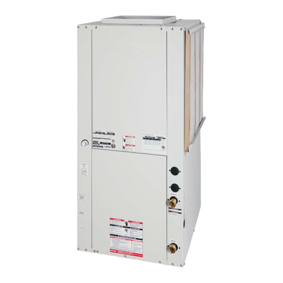
- Page 1 Installation, Operation and Maintenance HEH/HEV Series www.marsdelivers.com...
-
Page 2: Table Of Contents
HE Series Table of Contents Model Nomenclature General Information Unit Physical Data Horizontal Installation Field Conversion of Air Discharge Horizontal Installation Vertical Installation Piping Installation vFlow Heat Pump Applications Overview ® Water-Loop Heat Pump Applications Ground-Loop Heat Pump Applications Ground-Loop and Ground Water Heat Pump Applications Ground-Water Heat Pump Applications Water Quality Standards... -
Page 3: Model Nomenclature
Installation, Operation & Maintenance - HEH/HEV Series Model Nomenclature 4 5 6 0 3 6 MODEL TYPE HE = HEAT CONTROLLER RESIDENTIAL 410A CONFIGURATION H = HORIZONTAL V = VERTICAL SUPPLY AIR OPTIONS B = BACK DISCHARGE, HORIZONTAL ONLY UNIT SIZE T = TOP DISCHARGE, VERTICAL ONLY S = STRAIGHT DISCHARGE, HORIZONTAL ONLY RETURN AIR OPTIONS... - Page 4 Installation, Operation & Maintenance - HEH/HEV Series Storage Pre-Installation General Information Safety � WARNING! � Warnings, cautions, and notices appear throughout this manual. Read these items carefully before attempting WARNING! All refrigerant discharged from this unit must any installation, service, or troubleshooting of the be recovered WITHOUT EXCEPTION.
-
Page 5: General Information
Installation, Operation & Maintenance - HEH/HEV Series General Information Examine all pipes, fittings, and valves before installing � CAUTION! � any of the system components. Remove any dirt or debris found in or on these components. CAUTION! All three phase scroll compressors must have direction of rotation verified at start-up. -
Page 6: Unit Physical Data
Installation, Operation & Maintenance - HEH/HEV Series Unit Physical Data Two-Stage HE Series (60Hz Only) Model Compressor (1 Each) Scroll Factory Charge HFC-410A (oz) ECM Fan Motor & Blower Fan Motor (hp) Blower Wheel Size (dia x w) - (in) 10X10 11X10 Water Connection Size... -
Page 7: Horizontal Installation
Installation, Operation & Maintenance - HEH/HEV Series Horizontal Installation Horizontal Unit Location Mounting Horizontal Units Units are not designed for outdoor installation. Locate Horizontal units have 4 hanger brackets partially attached the unit in an INDOOR area that allows enough space at the factory, one at each corner. - Page 8 Installation, Operation & Maintenance - HEH/HEV Series Horizontal Installation Figure 2: Horizontal Unit Pitch 1/4” (6.4mm) pitch toward drain for drainage Drain Connection Figure 3: Typical Horizontal Unit Installation 3/8” [10mm] thread rods (by others) Thermostat Stainless Steel Wiring Braid Hose with Integral “J”...
-
Page 9: Field Conversion Of Air Discharge
Installation, Operation & Maintenance - HEH/HEV Series Field Conversion of Air Discharge Figure 4: Left Return Side to Back Overview - Horizontal units can be field converted between side (straight) and back (end) discharge using Remove Screws Water Connection End the instructions below. -
Page 10: Horizontal Installation
Installation, Operation & Maintenance - HEH/HEV Series Horizontal Installation Figure 6: Horizontal Condensate Connection Condensate Piping - Horizontal Units - A condensate drain line must be installed and pitched away for the unit to allow for proper drainage. This connection must meet 2”... -
Page 11: Vertical Installation
Installation, Operation & Maintenance - HEH/HEV Series drops below the dew point (insulation is required for ground loop applications in most climates). Pipe joint compound is not necessary when Teflon thread tape is pre-applied to hose assemblies or when flared-end ®... - Page 12 Installation, Operation & Maintenance - HEH/HEV Series Vertical Installation Notice! Installation Note - Ducted Return: Many horizontal WSHPs are installed in a return air ceiling plenum application (above ceiling). Vertical WSHPs are commonly installed in a mechanical room with free return (e.g. louvered door).
-
Page 13: Piping Installation
Installation, Operation & Maintenance - HEH/HEV Series Piping Installation Installer Caution: After making water connections on Installation of Supply and Return Piping units equipped with ClimaDry II, ensure the three union Follow these piping guidelines. nuts on the internal three-way water valve are tight. 1. -
Page 14: Vflow ® Heat Pump Applications Overview
Installation, Operation & Maintenance - HEH/HEV Series vFlow Heat Pump Applications Overview ® vFlow is a revolutionary new, intelligent, and efficient an internal check valve for multiple unit installations. ® way to circulate water (or water plus antifreeze) using This pump is a factory installed option for the HE unit internal, variable speed water flow control. - Page 15 Installation, Operation & Maintenance - HEH/HEV Series vFlow Heat Pump Applications Overview - Continued ® Water Pressure Schrader Ports readings through these ports. The water flow through The pressure ports built in to the unit are provided as a the unit can be determined by measuring the water means of measuring pressure drop through the water-to- pressure at the “water pressure out”...
- Page 16 Installation, Operation & Maintenance - HEH/HEV Series High Head Variable Pump Performance...
-
Page 17: Water-Loop Heat Pump Applications
Installation, Operation & Maintenance - HEH/HEV Series Water-Loop Heat Pump Applications Commercial Water Loop Applications The piping system should be flushed to remove dirt, Commercial systems typically include a number of piping chips, and other foreign material prior to units connected to a common piping system. Any unit operation (see “Piping System Cleaning and Flushing plumbing maintenance work can introduce air into the Procedures”... -
Page 18: Ground-Loop Heat Pump Applications
Installation, Operation & Maintenance - HEH/HEV Series Ground-Loop Heat Pump Applications � CAUTION! � Test individual horizontal loop circuits before backfilling. Test vertical U-bends and pond loop assemblies prior to CAUTION! The following instructions represent industry installation. Pressures of at least 100 psi [689 kPa] should accepted installation practices for closed loop earth coupled be used when testing. -
Page 19: Ground-Loop And Ground Water Heat Pump Applications
Installation, Operation & Maintenance - HEH/HEV Series Ground-Loop and Ground Water Heat Pump Applications Ground-Loop Heat Pump Applications Typical Closed Loop with Central Pumping (unit with internal modulating water valve) To Thermostat Internal Motorized Modulating Valve Water Out Water In High and Low Voltage Shut Off... -
Page 20: Ground-Water Heat Pump Applications
Installation, Operation & Maintenance - HEH/HEV Series Ground-Water Heat Pump Applications Water Quality Standards - Table 3 should be consulted Open Loop - Ground Water Systems - Typical open loop piping is shown in accompanying illustration. Shut for water quality requirements. Scaling potential should be assessed using the pH/Calcium hardness method. - Page 21 Installation, Operation & Maintenance - HEH/HEV Series Ground-Water Heat Pump Applications Flow Regulation - Units without vFlow - Flow ® regulation can be accomplished by two methods. One method of flow regulation involves simply adjusting the ball valve or water control valve on the discharge line. Measure the pressure drop through the unit heat exchanger, and determine flow rate from Tables 8a through 8e.
-
Page 22: Water Quality Standards
Installation, Operation & Maintenance - HEH/HEV Series Water Quality Standards Table 3: Water Quality Standards Water Quality Closed Open Loop and Recirculating Well Parameter Material Recirculating Scaling Potential - Primary Measurement Above the given limits, scaling is likely to occur. Scaling indexes should be calculated using the limits below pH/Calcium Hardness pH <... -
Page 23: Electrical - Line Voltage
Installation, Operation & Maintenance - HEH/HEV Series Electrical - Line Voltage Electrical - Line Voltage - All field installed wiring, � WARNING! � including electrical ground, must comply with the National WARNING! To avoid possible injury or death due to electrical Electrical Code as well as all applicable local codes. - Page 24 Installation, Operation & Maintenance - HEH/HEV Series Electrical - Line Voltage Units with Modulating Motorized Valve Compressor Voltage Min/Max Fan Motor Total Unit Min Circ Max Fuse/ Model Voltage Code Voltage HACR 208/230/60/1 197/252 11.7 58.3 15.6 18.5 265/60/1 239/292 54.0 12.3 14.6...
-
Page 25: Electrical Data
Installation, Operation & Maintenance - HEH/HEV Series Electrical Data Units with High Head Variable Pump Min/ Compressor Pump Total Voltage Model Voltage Motor Motor Unit Circ Fuse/ Code Voltage HACR 208/230/60/1 197/252 11.7 58.3 1.44 17.0 20.0 208/230/60/3 197/252 55.4 1.44 11.8 13.5... -
Page 26: Electrical - Power & Low Voltage Wiring
Installation, Operation & Maintenance - HEH/HEV Series Electrical - Power & Low Voltage Wiring Power Connection - Line voltage connection is made by � WARNING! � connecting the incoming line voltage wires to the “L” side of the contractor as shown in the unit wiring diagram. Consult WARNING! Disconnect electrical power source to prevent electrical data tables for correct fuse size. -
Page 27: Electrical - Low Voltage Wiring
Fan Enable Fan Speed Installation, Operation & Maintenance - HEH/HEV Series Test Electrical - Low Voltage Wiring Micro Alarm Figure 17: LT1 Limit Setting Figure 18: Accessory Wiring Relay Fault Status P2 Terminal Strip 6 1/2" Typical Factory low voltage Molex Water connection for Valve... -
Page 28: Electrical - Low Voltage Wiring For Non-Vflow ® Units Using External Motorized Water Valve
Installation, Operation & Maintenance - HEH/HEV Series Electrical - Low Voltage Wiring for non-vFlow Units Using External Motorized Water Valve ® Water Valve Wiring Figure 19: AVM Valve Wiring Figure 20: Taco SBV Valve Wiring DXM2 Taco Valve Heater Switch Aquastat Unidad Empacada Figure 21: Two-Stage Piping... -
Page 29: Electrical - Thermostat Wiring
Installation, Operation & Maintenance - HEH/HEV Series Figure 24a: Communicating Thermostat Connection to DXM2 Control Electrical - Thermostat Wiring iGate Thermostat ® DXM2 7602-457 Thermostat Installation - The thermostat should be of the back plate. Mark the position of the back plate 24Vac Common Comm + located on an interior wall in a larger room, away from... -
Page 30: Blower Performance Data
Installation, Operation & Maintenance - HEH/HEV Series Blower Performance Data HE Standard Unit - No Reheat Cooling Mode Dehumid Mode Heating Mode Max ESP Fan Only Aux Emerg Model Motor Range (in wg) Mode Mode (hp) Stg 2 Stg 1 Stg 2 Stg 1 Stg 2... -
Page 31: Ecm Blower Control
Installation, Operation & Maintenance - HEH/HEV Series ECM Blower Control The ramp down feature is eliminated during an ESD The ECM fan is controlled directly by the DXM2 control (Emergency Shut Down) situation. When the DXM2 board that converts thermostat inputs and CFM settings ESD input is activated, the blower and all other control to signals used by the ECM motor controller. -
Page 32: Typical Wiring Diagram - Single Phase Units
Installation, Operation & Maintenance - HEH/HEV Series Typical Wiring Diagram - Single Phase Unit... -
Page 33: Typical Wiring Diagram - Three Phase Units
Installation, Operation & Maintenance - HEH/HEV Series Typical Wiring Diagram - Three Phase Unit... - Page 34 Installation, Operation & Maintenance - HEH/HEV Series Typical Wiring Diagram - 460 Volt Unit...
-
Page 35: Dxm2 Controls
Installation, Operation & Maintenance - HEH/HEV Series DXM2 Controls DIP Switches – Note: In the following field configuration DXM2 Control - For detailed control information, see DXM2 Application, Operation and Maintenance (AOM) options, DIP switches should only be changed when manual (part # 97B0003N15). - Page 36 Installation, Operation & Maintenance - HEH/HEV Series DXM2 Controls On = Normal fan mode. Off = Dehumidification mode. Table 7a: Accessory DIP Switch Settings 1.6 – DDC output at EH2: DIP 1.6 provides selection DIP 2.1 DIP 2.2 DIP 2.3 ACC1 Relay Option for DDC operation.
- Page 37 Installation, Operation & Maintenance - HEH/HEV Series DXM2 Controls Table 7b: LED and Alarm Relay Output Table DMX2 CONTROLLER FAULT CODES DMX2 Fault and Status LED Operation Fault LED Status LED Alarm Relay with Test Mode Not Active (Red) (Green) DXM2 Is Non-Functional Off...
-
Page 38: Dxm2 Layout And Connections
Installation, Operation & Maintenance - HEH/HEV Series DXM2 Layout and Connections Communicating Service tool 5" stat connection connection (240Vac) A+ 24V (240Vac) N.C. N.O. N.O. Fan Enable Fan Speed Test Button Conventional stat connection to Speed up Time Delays Test ECM Motor Connection Water Coil... - Page 39 Installation, Operation & Maintenance - HEH/HEV Series DXM2 Controls 5" DXM2 Control Start-up Operation – The control will not Figure 26b: Test Mode Button operate until all inputs and safety controls are checked for normal conditions. The compressor will have a 5 (240Vac) (240Vac) A+ 24V...
- Page 40 Installation, Operation & Maintenance - HEH/HEV Series DXM2 Controls Table 8: Nominal Resistance at Various Temperatures DXM2 Thermostat Details Thermostat Compatibility – Most heat pump and heat/ Resistance Resistance Temp (ºC) Temp (ºF) Temp (ºC) Temp (ºF) (kOhm) (kOhm) cool thermostats can be used with the DXM2, as well as -17.8 85.34 131.0...
-
Page 41: Unit Starting And Operating Conditions
Installation, Operation & Maintenance - HEH/HEV Series Unit Starting and Operating Conditions Operating Limits Environment – Units are designed for indoor installation only. Never install units in areas subject to freezing or where humidity levels could cause cabinet condensation (such as unconditioned spaces subject to 100% outside air). Power Supply –... -
Page 42: Piping System Cleaning And Flushing
Installation, Operation & Maintenance - HEH/HEV Series Piping System Cleaning and Flushing Piping System Cleaning and Flushing - Cleaning and 10. When the system is successfully cleaned, flushed, refilled and bled, check the main system panels, flushing the WLHP piping system is the single most safety cutouts and alarms. -
Page 43: Unit And System Checkout
Installation, Operation & Maintenance - HEH/HEV Series Unit and System Checkout SYSTEM CHECKOUT � WARNING! � � System water temperature: Check water temperature WARNING! Polyolester Oil, commonly known as POE oil, is for proper range and also verify heating and cooling a synthetic oil used in many refrigeration systems including set points for proper operation. -
Page 44: Unit Start-Up Procedure
Installation, Operation & Maintenance - HEH/HEV Series Unit Start-Up Procedure Unit Start-up Procedure 6. Allow five (5) minutes between tests for pressure to 1. Turn the thermostat fan position to “ON”. Blower equalize before beginning heating test. should start. a. Adjust the thermostat to the lowest setting. Place 2. - Page 45 Installation, Operation & Maintenance - HEH/HEV Series Unit Operating Conditions Table 10: HE Coax Water Pressure Drop � WARNING! � Pressure Drop (psi) Model WARNING! When the disconnect switch is closed, high 30°F* 50°F 70°F 90°F voltage is present in some areas of the electrical panel. Exercise caution when working with energized equipment.
-
Page 46: Unit Operating Conditions
Installation, Operation & Maintenance - HEH/HEV Series Unit Operating Conditions Table 11: HE Series Typical Unit Operating Pressures and Temperatures (60Hz – I-P Units) Full Load Cooling - without HWG active Full Load Heating - without HWG active Entering Water Suction Discharge Water... - Page 47 Installation, Operation & Maintenance - HEH/HEV Series Unit Operating Conditions Full Load Cooling - without HWG active Full Load Heating - without HWG active Entering Water Suction Discharge Water Suction Discharge Water Air Temp Air Temp Water Flow Pressure Pressure Superheat Subcooling Temp Rise...
-
Page 48: Preventive Maintenance
Installation, Operation & Maintenance - HEH/HEV Series Preventive Maintenance Water Coil Maintenance - (Direct ground water especially important to provide consistent washing of these filters (in the opposite direction of the normal air applications only) If the system is installed in an area with flow) once per month using a high pressure wash similar a known high mineral content (125 P.P.M. -
Page 49: Troubleshooting
Installation, Operation & Maintenance - HEH/HEV Series Troubleshooting General Outputs If operational difficulties are encountered, perform The compressor and reversing valve relays are 24VAC the preliminary checks below before referring to the and can be verified using a voltmeter. For units with troubleshooting charts. - Page 50 Installation, Operation & Maintenance - HEH/HEV Series Troubleshooting (Continued) Advanced Diagnostics If a communicating thermostat or diagnostic tool (7602-444) is connected to the DXM2, additional diagnostic information and troubleshooting capabilities are available. The current status of all DXM2 inputs can be verified, including the current temperature readings of all temperature inputs.
-
Page 51: Dxm2 Process Flow Chart
Installation, Operation & Maintenance - HEH/HEV Series DXM2 Process Flow Chart � WARNING! � WARNING! HAZARDOUS VOLTAGE! DISCONNECT ALL ELECTRIC POWER INCLUDING REMOTE DISCONNECTS BEFORE SERVICING. Failure to disconnect power before servicing can cause severe personal injury or death. DXM2 Functional Start Troubleshooting Flow Chart Did Unit... -
Page 52: Functional Troubleshooting
Installation, Operation & Maintenance - HEH/HEV Series Functional Troubleshooting Fault Htg Clg Possible Cause Solution Check line voltage circuit breaker and disconnect. Check for line voltage between L1 and L2 on the contactor. Main power problems Green Status LED Off Check for 24VAC between R and C on CXM/DXM' Check primary/secondary voltage on transformer. - Page 53 Installation, Operation & Maintenance - HEH/HEV Series Functional Troubleshooting (cont.) Fault Htg Clg Possible Cause Solution Check for dirty air filter and clean or replace Reduced airflow in cooling, ClimaDry, or Check fan motor operation and airflow restrictions constant fan Low Air Coil Temperature Too high of external static - check static vs blower table Fault - (ClimaDry) Code 12...
-
Page 54: Performance Troubleshooting
Installation, Operation & Maintenance - HEH/HEV Series Performance Troubleshooting Symptom Htg Clg Possible Cause Solution Dirty filter Replace or clean Check for dirty air filter and clean or replace Reduced or no air flow Check fan motor operation and airflow restrictions in heating Too high of external static - check static vs blower table Check for dirty air filter and clean or replace... - Page 55 Check pump operation or water valve operation/setting Reduced water flow Plugged strainer or filter - clean or replace in heating Check water flow adjust to pr oper flow rate Installation, Operation & Maintenance - HEH/HEV Series Water temperature out of range Bring water temp within design parameters Check for dirty air filter and clean or replace Low Suction Pressure...
-
Page 56: Start-Up Log Sheet
Installation, Operation & Maintenance - HEH/HEV Series Start-Up Log Sheet Installer: Complete unit and system checkout and follow unit start-up procedures in the IOM. Use this form to record unit information, temperatures and pressures during start-up. Keep this form for future reference. Job Name: Street Address: Model Number:... -
Page 57: Functional Troubleshooting
Location: ________________________ Model Number: ________________________ Installation, Operation & Maintenance - HEH/HEV Series Serial Number: ________________________ Date: ________________________ Packaged Unit Refrigeration Schematic Customer: _____________________________________ Antifreeze: ________________________ Functional Troubleshooting Model#: ________________________ Serial#: ________________ Loop type: _______________ Complaint: ________________________________________________________________________ Refrigerant Circuit Diagrams HEATING CYCLE ANALYSIS - °F SUCTION COIL... -
Page 58: Warranty (U.s. & Canada)
MARS installation instructions and in accordance with all local, state and warranty period, MARS shall have the right to allow a credit in the amount of national codes for normal use. -
Page 59: Revision History
Installation, Operation & Maintenance - HEH/HEV Series Revision History Date: Item: Action: 1/23/19 High Head Variable Pump update Pages 15,16, 25 11/7/18 Updated warter circuit options Decoder 10/26/18 Decoder Added disconnect to control 07/25/17 Update hanger and mounting instructions Page 7 10/7/16 Page 7 Text Update... - Page 60 1900 Wellworth Ave., Jackson, MI 49203 • Ph. 517-787-2100 • www.marsdelivers.com 9/2020...
Need help?
Do you have a question about the Comfort-Aire Century HE Series and is the answer not in the manual?
Questions and answers