Table of Contents
Advertisement
Quick Links
Advertisement
Table of Contents

Related Manuals for Booma-RC Wallaby Switch


Summary of Contents for Booma-RC Wallaby Switch
- Page 1 Booma RC Wallaby Switch www.boomarc.com...
- Page 2 Congratulations for choosing the Booma RC Wallaby Switch. Wallaby Switch was designed for giant scale RC enthusiasts by giant scale RC enthusiasts. Wallaby Switch offers features never seen before in Radio Control applications in a compact, light weight and affordable package.
- Page 3 DO’S DON’TS DO NOT use Wallaby Switch dual battery version with batteries of different voltages or different battery chemistries unless you are an advanced user that is aware of the consequences. Mixing of different battery voltages or chemistry types when using Wal- laby Switch may cause the battery with the highest voltage to be consumed first.
- Page 4 Typical Connection Examples for Wallaby Switch. Dual Battery and Dual Receiver System Wallaby Battery 1 Receiver 1 Wallaby Switch Switch Input Built in Dual Battery Isolator circuit Wallaby Battery 2 Receiver 2 Switch Input Dual Battery Redundant System Battery 1...
-
Page 5: Let's Get Started
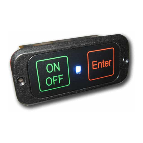
Wallaby Switch Outputs Battery Inputs Wallaby Switch Outputs As you connect the battery or batteries to Wallaby Switch the LED indicator will flash slowly THREE times. This indicates that all is OK. If the LED starts to flash rapidly this is an indication of incorrect battery type or a low voltage on one of the connected batteries. - Page 6 Turning Wallaby Switch ON and OFF Enter Wallaby Switch is supplied with 1 or 2 x fail-safe switches (de- pending on the selected model). As long as power is supplied to Wallaby Switch it will hold the state of the switch. Wallaby Switch also comes with additional protection circuitry to avoid an accidental ON or OFF state.
-
Page 7: Sleep Mode
Switch will go into a sleep mode using only 0.4mA to conserve power. You can leave Wallaby Switch connected to the batteries however it is advisable to disconnect Wallaby Switch from the bat- teries if storing your model for a long period. - Page 8 Template Cutout for Wallaby Switch 17 mm...
-
Page 9: Battery Selection
IMPORTANT - DO NOT MIX BATTERY CHEMISTRY WHEN USING Wallaby Switch. ALWAYS USE BATTERIES OF THE SAME CHEMIS- TRY AND CAPACITY. How To Calibrate - connect both batteries to Wallaby Switch and wait until the system check is complete (three slow flashes). Press and hold the RED “ENTER”... -
Page 10: Battery Monitoring
Once you have calibrated Wallaby Switch with the correct bat- tery type it will monitor the output voltage of your battery(s) If a low voltage is seen by Wallaby Switch from either battery then Wallaby Switch will flash the Blue LED in rapid bursts. This is an indication that something is wrong and should be investi- gated. - Page 11 Battery Capacity DO NOT EVER try to get the full mA capacity out of your batteries! An attempt to do this may end in disaster. Wallaby Switch meters consumption conservatively but NEVER OPERATE YOUR MODEL WITH A LOW VOLTAGE CONDITION.
- Page 12 Template Cutout for Wallaby Switch 17 mm...
- Page 13 Current capacity will then be limited to Wallaby Switch design. Using Wallaby Switch with a voltage regulator Wallaby Switch was designed to work with all current RC products regulated and unregulated. If you prefer using LifeP04 chemistry batteries (nominal 6.4v) then Wallaby Switch will work excellently in most RC and Robotics applications without a regulator.
-
Page 14: Specifications
Specifications - 2 x independent switching circuits in a double pole single throw combination. - Battery chemistry LifeP04 (2 - 3 cells), LiPo Life (2 - 3 cells), Lion (2 - 3 cells). - Maximum input voltage 13 volts. - Minimum input voltage 6 volts - Max continuous current: 2 x 10 Amp (20 Amp), 2 x 20 Amp (40 Amp for 30 sec),... - Page 15 Booma RC Ignition (Iggy) Switch Booma RC DualBat Booma RC Intelliswitch...
- Page 16 Notes...
Need help?
Do you have a question about the Wallaby Switch and is the answer not in the manual?
Questions and answers