
Related Manuals for DURAG D-R 800


Summary of Contents for DURAG D-R 800
- Page 1 D−R 800 Dust concentration meter Before starting any work, read the operating instructions (the manual)! Kollaustraße 105 · 22453 Hamburg · www.durag.de GmbH 115 550 Article No.:...
- Page 2 Reference addresses can be found on page 153. or parts thereof may not be reproduced or distributed without express permission from DURAG GmbH, irrespective of how this is done, in what language or by what medium, electronic or mechanical.
- Page 3 Contents Contents Foreword General Brief overview of the contents Typographical conventions Meaning of the warnings and instructions used Safety instructions General safety instructions Responsibility of the operating company Avoidance of consequential damage in the event of a system fault Hazards due to electrical equipment Hazard due to laser light Hazard due to hot, aggressive or explosive gases or high pressure of the measurement Hazard to the device due to purge air failure...
- Page 4 Contents Layout and function Functional description of the system components Functional diagram Supply unit Configuration, installation, commissioning Safety Installation Installation Commissioning Optional accessories, installation and use Purge air heating Purge air monitoring Weather protection hood Modbus Modbus register definitions Operation Menu structure Edit mode: Brief commands...
-
Page 5: Table Of Contents
Standards and regulations Declaration of Conformityand QAL1 Glossary Index DURAG GROUP company addresses Figures Figure 4.1: Position of the rating plates....................35 Figure 4.2: Supply unit (above) (measurement) probe (below) ............... 37 Figure 4.3: Vertical measuring probe for vertical ducts................38 Figure 4.4: Horizontal measuring probe for horizontal ducts .............. - Page 6 Contents Figure 7.13: Dimensional drawing (optional) weather protection hood ............ 79 Figure 7.14: Dimensional drawing (optional) weather protection hood for purge air heater ....80 Figure 7.15: Activation of the Modbus terminating resistor on the D−R 800 printed circuit board no. 2.. 83 Figure 8.1: Menu structure: vertical: Main menu ..................
- Page 7 Foreword Foreword This manual is intended to assist you in starting to use your DURAG product. In this publication you will find information and technical data for planning, installation / commissioning, operation and maintenance of the D−R 800. The functional diagram for the overall equipment and the device components, together with a spare parts list complete this information.
- Page 9 D−R 800 Dust concentration meter General Brief overview of the contents Typographical conventions Meaning of the warnings and instructions used...
- Page 11 The DURAG Group has a policy of continuous development of its products, to bring you the optimum benefits from the devices you have procured. Therefore please understand that the product may vary in some respects from the descriptions in the manual.
- Page 12 General 1.2 Typographical conventions In order to make the text of this manual clear, text elements such as safety instructions, warnings, tips, keyboard symbols, menu addresses etc. are displayed differently. The following conventions apply in this manual: Safety instructions and warnings appear in this manual as follows: WARNING Hazard due to electrical equipment Before removing any casings or guards, deenergise the devices.
- Page 13 General WARNING Disregard of instructions so marked can lead to serious injuries or damage to property. > To avoid injuries and to ensure safe operation of the system, comply with all "WARNING" instructions. CAUTION Disregard of instructions so marked can lead to minor injuries or damage to property..
- Page 15 D−R 800 Dust concentration meter Safety instructions General safety instructions Responsibility of the operating company Avoidance of consequential damage in the event of a system fault Hazards due to electrical equipment Hazard due to laser light Hazard due to hot, aggressive or explosive gases or high pressure of the measurement Hazard to the device due to purge air failure Use for the intended purpose Qualified personnel...
- Page 17 Disregard of operating instructions and safety instructions shown in this manual can lead to significant hazards. 2.1 General safety instructions The DURAG Dust concentration meter D−R 800 is designed and built to current technology and satisfies the recognised safety regulations. Despite this, hazards can arise.
- Page 18 Safety instructions The device as an entity and also its individual components may be used only when in their original configuration. 2.2 Responsibility of the operating company The Dust concentration meter is intended for use in commercial operations. The operating company of the Dust concentration meter is subject therefore to the statutory duties of safety at work, coupled with the applicable guidelines, statutes and standards.
- Page 19 Safety instructions 2.4 Hazards due to electrical equipment This device is powered by electricity. Therefore only suitably qualified personnel may work on it. These personnel must be thoroughly familiar with all danger sources and repair measures in accordance with these operating instructions. Risk of fatal injury due to electrical power! DANGER There is a risk of immediate fatal injury if live components are touched.
- Page 20 Safety instructions 2.5 Hazard due to laser light CAUTION Danger due to laser light! There is a risk of blinding! Laser protection class II (radiation power < 1 mW at 655 nm) is guaranteed only at the unmodified (sealed) manufacturer's setting of the laser potentiometer.
- Page 21 2.9 Qualified personnel The operating company's personnel who are responsible for safety must ensure that work on DURAG devices or systems is only carried out by qualified skilled personnel, whose competence has been checked by responsible experts.
- Page 22 Knowledge of system conditions, applicable standards, provisions and accident prevention regulations. Knowledge of local conditions, guidelines and operating instructions for working in explosion hazard areas. Sufficient knowledge of the system D−R 800. DURAG offers appropriate training courses in this respect. D−R 800...
- Page 23 D−R 800 Dust concentration meter Brief information Safety Brief instructions Calibration Operation...
- Page 25 Damage to electronic components due to electrostatic discharge (ESD) DURAG devices are enclosed in a casing, and thus protected against uncontrolled electrostatic discharge (ESD). Suitable ESD protective measures must be taken before the device is opened (e.g. for service or maintenance work).
- Page 26 Brief information CAUTION Damage to property by unauthorised personnel The person responsible for safety must ensure that only qualified (authorised) personnel operate the measuring system described in this manual. Particular care must be taken to ensure that the warnings on protection of personnel and protection of the measuring system specified in this manual are known and complied with.
- Page 27 Brief information 3.4 Operation Use the keys + and to move to the desired menu branches. The fields in the main menu (vertical) are shown by a list symbol in the bottom left corner of the display. You can move between the main menu (vertical) and the submenus (horizontal) by pressing the MOD key.
- Page 29 D−R 800 Dust concentration meter Product description Scope of supply Accessories Instructions for delivery Instructions about the product Conformity/approvals Instructions on warranty Limitations of liability Disposal of the D−R 800 Identification of the product 4.10 Device description 4.11 Application areas 4.12 Terminology 4.13...
- Page 31 Product description Product description In this section you will find information on scope of supply, accessories, approvals, warranty, fields of application - in short, everything relating to the D−R 800. 4.1 Scope of supply Scope of supply of the standard overall system D−R 800: depending on what was ordered one of the following measuring probes: Measuring probe...
- Page 32 Product description 4.2 Accessories Accessories D−R 800: Purge air heater, consisting of: heater, bracket, hose connection to the measuring probe and connection cable to the connection unit (length 10 m) for 200-264 VAC, 500 W 115425 for 100-132 VAC, 500 W 115539 purge air monitoring, consisting of: Air flow monitoring unit with sensory electronics,...
- Page 33 If any external damage in transport is evident: 1. Immediately complain to the carrier and to the DURAG GROUP (DURAG GROUP company addresses) see page 153. 2. Grant the delivery only qualified acceptance.
- Page 34 141. 4.6 Instructions on warranty The warranty for the devices of the DURAG GROUP is generally 12 months from date of delivery. All obligations result from the respective sales contract, which also contains the complete and sole authorised warranty provisions ("Conditions of supply for goods and services in the electrical industry"...
-
Page 35: Figure 4.1: Position Of The Rating Plates
Product description 4.8 Disposal of the D−R 800 Your contribution to the correct disposal of this product protects the environment and the health of your fellow man. Materials recycling helps reduce the consumption of raw materials. You can obtain current information on the recycling of this product from your local authority. - Page 36 Low voltages that are connected must also be generated with safe separation. 4.11 Application areas The DURAG D−R 800 described in this manual is a device for monitoring dustemissions in applications such as. Power stations and cement works ...
-
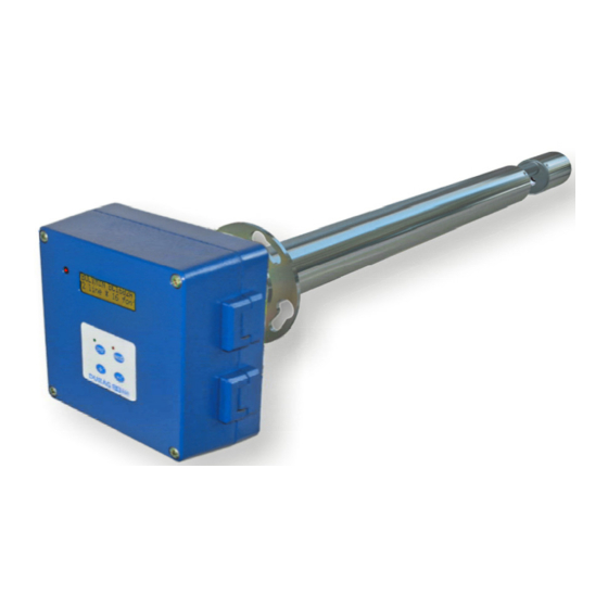
Page 37: Figure 4.2: Supply Unit (Above) (Measurement) Probe (Below)
Product description 4.12 Terminology The D−R 800 consists essentially of: Probe Supply unit Installation tubes with flange Accessories such as purge air hoses and minor fittings A Blower F Casing with evaluation unit B Filter housing G Lance Electrical and data connections for C Purge air intake... -
Page 38: Figure 4.3: Vertical Measuring Probe For Vertical Ducts
The yellow sealing cap for the cleaning aperture (shown above) is on the left of the device! D-R 800 SYS V… (shown above left): The (blue) arrows in the duct show the possible directions of gas flow. The red dot on the device lies parallel to the red dot on the welded-in flange! Both dots are in the upper position. - Page 39 D−R 800 Dust concentration meter Layout and function Functional description of the system components Functional diagram Supply unit 5.3.1 Layout of the supply unit 5.3.2 Purge air heater (optional) 5.3.3 Purge air monitoring (optional)
-
Page 41: Figure 5.1: Components Of The D−R 800
In addition, the device can be integrated via the supply unit with bus the interface into an environmental and process data management system (e.g. DURAG D-EMS 2000). Exhaust gas duct, stack E Exhaust gas, flue gas... -
Page 42: Figure 5.2: Functional Diagram I
Layout and function 5.2 Functional diagram The measuring device D−R 800 operates according to the () forward scattering principle. The concentrated and modulated light of a laser diode penetrates the measuring volume. The light scattered by the dust particles is largely scattered forwards, therefore the receiving lens is positioned here. -
Page 43: Figure 5.4: Layout Of The Supply Unit
Layout and function for converting scattered light into mg/m³ must be entered. However this does not affect the current outputs, limit values etc.. A pollution measurement is performed every 5 min in order to record dust deposits on the optical boundary surfaces and the ageing of the optical elements. 5.3 Supply unit 5.3.1 Layout of the supply unit The power supply for the measuring head contains... -
Page 44: Purge Air Heater (Optional)
Layout and function 5.3.2 Purge air heater (optional) The purpose of the (optional) purge air heater is to heat up the purge air to 40°C max. This option is required only if the local climatic conditions mean that the minimum temperature listed in the checklist in section 6.2.1 (from page 48) for the purge air supply may not be attained. - Page 45 D−R 800 Dust concentration meter Configuration, installation, commissioning Safety Installation 6.2.1 Preconditions for use 6.2.2 Transport 6.2.3 Installation location, place of use Installation 6.3.1 Weldingin the flange 6.3.2 Connection Power supply, operating media Commissioning 6.4.1 Measures before initial commissioning 6.4.2 Commissioning...
-
Page 47: D−R
Damage to electronic components due to electrostatic discharge (ESD) DURAG devices are enclosed in a casing, and thus protected against uncontrolled electrostatic discharge (ESD). Suitable ESD protective measures must be taken before the device is opened (e.g. for service or maintenance work). -
Page 48: Installation
Is the measuring point in a duct You need a measuring probe □ that runs vertically? D-R 800 SYS V… Is the measuring point in a duct You need a measuring probe □ that runs horizontally? D-R 800 SYS HO…... -
Page 49: Table 6.1: Checklist: Preconditions For The Operation Of The D−R 800
Configuration, installation, commissioning Is suitable purge air available? The fresh air drawn in by the supply □ unit for the purge air supply must be free of dust and oil, and have a temperature between -20 and +40°C. purge air heating (see page 43) should be provided if necessary. -
Page 50: Figure 6.1: Selection Of The Correct Flange / Lance Length
Configuration, installation, commissioning Instructions for selection of the correct flange / lance length Flue size Flange tube length Flue wall / insulation (Measuring) lance length ÜF Flange tube projection 30 mm Flange tube Flue size Flange tube length Flue wall / insulation (Measuring) lance length ÜF Flange tube projection 30 mm... -
Page 51: Figure 6.2: Dimensionaldrawing (Measuring )Probe
Configuration, installation, commissioning Figure 6.2: Dimensionaldrawing (measuring )probe 6.2.2 Transport The laser in the probe is optically calibrated, therefore avoid impacts to the measuring probe. If due to rough treatment the measuring light beam does not reach the receiving unit coherently, the measuring result will be corrupted. Wherever possible, use the original packaging for transport: The moulded packing is designed to ensure safe transport. -
Page 52: Figure 6.3: Installation Point Of The Probe; Upstream Section
Configuration, installation, commissioning The installation location should be as free of vibrations and oscillations as pos- sible. If this is not possible, the device should be installed so that it is insulated from any vibrating suction draught, so that the measuring system is not affected. Figure 6.3: Installation point of the probe;... -
Page 53: Figure 6.5: Welding-In Drawing D−R 800 For A Horizontal Duct
Configuration, installation, commissioning If there is not enough space available, the upstream section (A) should be longer than the downstream section (B) in the ratio 2:1. 6.3 Installation 6.3.1 Weldingin the flange The welding in of a welded-in flange is different in a vertical flue from a horizontal flue. -
Page 54: Figure 6.7: Dimensional Drawing For The Supply Unit D−R 800
6.3.2 Connection Power supply, operating media Install the supply unit. All external connections of the DURAG Dust concentration meter are made via the supply unit. Power supply, data interface and purge air supply are located in this unit. -
Page 55: Figure 6.8: Changing The Fuse In The Supply Unit D−R 800
Configuration, installation, commissioning As the purge air is made available in the supply unit (2), the device casing must be sealed airtight. For this reason the casing door is sealed with a rubber bead and the unused cable ports are closed with plugs. (A) Intake ferrule for purge air (B) Purge air hose (C) Purge air restrictor (see Installation, purge air supply from page 58) -
Page 56: Figure 6.9: Wiring Diagram Of The Supply Unit D−R 800
Configuration, installation, commissioning Figure 6.9: Wiring diagram of the supply unit D−R 800 Cable specification Modbus () see section 7.4.4 from page 82 D−R 800... -
Page 57: Table 6.3: Terminal Assignment
Configuration, installation, commissioning Terminal assignment Terminal Function 230 VAC Relay 5 – 11 Purge air Relay 5 16 A monitoring Relay 5 – 14 750VA 230 VAC Relay 4 – 11 e.g. Relay 4 16 A limit value 2 Relay 4 – 14 750VA 230 VAC Relay 3 –... -
Page 58: Figure 6.10: Purge Air Connection Supply Unit
Configuration, installation, commissioning The two potential-free current outputs 1/2 and 3/4 are active and have an common earth potential. The current input 5/6 is active and is intended for direct connection to an optional temperature transmitter. The earth potential is at that of the supply. Installation, purge air supply The purpose of the purge air is to protect the module mounted on the dust duct. -
Page 59: Figure 6.11: Purge Air Connection Measurement Unit
Configuration, installation, commissioning Purge air Pressure (flue pressure) [ hPa] restrictor Size of the opening Ø 5.0 mm Ø 6.5 mm Ø 10.5 mm Table 6.4: Selection of the purge air restrictor The (optionally available) purge air monitoring can also contribute to security when selecting the correct purge air restrictor. - Page 60 Configuration, installation, commissioning The two connections on the measuring probe must not be switched over. Otherwise the supply of purge air could not reach the measuring probe, and the transmitting/receiving unit would quickly be irreversibly damaged by overheating and dust. Never push the measuring probe into the dust duct without switching on the purge air supply! The purge air hose is designed for a maximum ambient temperature of...
-
Page 61: Table 6.5: Checklist: Preconditions For Commissioning The D−R 800
Configuration, installation, commissioning 6.4 Commissioning 6.4.1 Measures before initial commissioning Are the preconditions for operation satisfied? Is the supplied dust measuring probe suitable for the existing duct in □ respect of its gas flow orientation (horizontal, vertical flow direction, see section Equipment on page 38)? For a system that has been correctly configured and installed the red dots on the probe flange and the welded-in flange should be alongside each other in the upper position. -
Page 62: Figure 6.12: Diaphragm Openings
Configuration, installation, commissioning 6.4.2 Commissioning First plug in the connection cable to the measuring probe, using the plug connector and secure it with the cap nut. The cap nut screwed connection is sealed with a rubber ring. The nut must be well tightened against the resistance of this rubber ring, to make sure of a reliable seal at the connection. -
Page 63: Figure 6.14: Evaluation Unit With Display And Controls
Configuration, installation, commissioning Each time it is switched on, the device performs a self-check and a reference measurement. During this process, "I24 Initial" appears on the display and flashes. Measurement is then started immediately, and the current dust concentration (A01) is shown on the display. Figure 6.14: Evaluation unit with display and controls The designations used here, such as "(A01)"... - Page 65 Dimensional drawing for the weather protection hood for purge air heater Modbus 7.4.1 General information on the Modbus protocol 7.4.2 Technische Beschreibung DURAG Modbus für D−R 800 7.4.3 Setting addresses (slave addresses) 7.4.4 Type of cabling, cross-section, max. length of the Modbus cables used 7.4.5...
-
Page 67: Figure 7.1: Installation Of The Purge Air Heating I
Damage to electronic components due to electrostatic discharge (ESD) DURAG devices are enclosed in a casing, and thus protected against uncontrolled electrostatic discharge (ESD). Suitable ESD protective measures must be taken before the device is opened (e.g. for service or maintenance work). -
Page 68: Figure 7.2: Installation Of The Purge Air Heating Ii
Optional accessories, installation and use 2. The instantaneous heater of the purge air heating is now fastened to the mounting plate using the four remaining socket head screws (Figure 7.1-A). The purge air hose from the supply unit (outlet) is connected to the hose gland at the purge air heating (Figure 7.2-E, inlet) and secured with a hose clip. -
Page 69: Figure 7.3: Installation Of The Purge Air Heating Iii (Electrical Connection)
Optional accessories, installation and use Figure 7.3: Installation of the purge air heating III (electrical connection) Note that the (miniature) fuse in the supply unit protects only the probe electronics and the purge air blower. The protection of the purge air heating is generally provided by the fuse in the power supply cable to the supply unit (see section Installation, electrical connection from page 55). -
Page 70: Figure 7.4: Purge Air Heater Internal Control Loop
Optional accessories, installation and use If the optional flow rate and temperature monitoring is not used, no fault message! will be received in the event of failure of the purge air heater. The instantaneous heater can be reset (put back in operation) after the overheating protection has tripped only by manual intervention. -
Page 71: Figure 7.5: (Optional) Weather Protection Hood Purge Air Heater
Optional accessories, installation and use L Knurled screws fastening the weather protection hood Q Recess for welded-in tube R Welded-in tube Figure 7.5: (optional) weather protection hood purge air heater L Knurled screws fastening the weather protection hood M Weather protection hood N Retaining plate for weather protection hood O Purge air heater bracket... -
Page 72: Figure 7.7: Adjustment Of The Purge Air Heater I
Optional accessories, installation and use Adjustment of the purge air heater 1. Undo the four M8 screws on the cover of the red protective casing, and remove the cover. Figure 7.7: Adjustment of the purge air heater I This allows access to the two temperature adjusters, which are wired in series. Temperature limiter Temperature controller Figure 7.8: Adjustment of the purge air heater II... -
Page 73: Figure 7.9: Dimensional Drawing Of The Purge Air Heater
Optional accessories, installation and use 7.1.2 Dimensional drawing of the purge air heater G 1 “ DIN ISO 228 ¼ ~400 Figure 7.9: Dimensional drawing of the purge air heater D−R 800... -
Page 74: Figure 7.10: Connection Of The Purge Air Monitoring Unit
Figure 7.10: Connection of the purge air monitoring unit Adjustment of the purge air monitoring The purge air monitoring unit is supplied by DURAG preset to the required flow rate range. After installation and electrical connection there is generally no need to adjust the purge air monitoring unit to the local flow conditions. -
Page 75: Figure 7.11: Local Adjustment Of The Purge Air Monitoring
Optional accessories, installation and use Operating mode display 2, 3 Setting keys for adjustment and configuration Figure 7.11: Local adjustment of the purge air monitoring The green LEDs show the current rate of flow (the LEDs 0 to 9 represent the range between zero flow and the set maximum rate of flow). -
Page 76: Table 7.2: Possible Causes / Remedies For "Error During Device Adjustment
Optional accessories, installation and use Release the key. The device is now adapted to the flow conditions. It switches to operating mode, and the devices display now appears as example 1 (Table 7.1). The adjustment affects the switching point: It is increased in proportion (to a maximum of LED 7). - Page 77 Optional accessories, installation and use If 2 s elapses without any key being pressed, the loads the new value and reverts to operating mode. Setting the temperature switching point (optional) Briefly press the key. > The device displayed the current temperature and the current setting of the switching point (temperature) in steps of 10°C for about 5 s.
-
Page 78: Figure 7.12: Dimensional Drawing Rate Of The Flow / Temperature Monitor
Optional accessories, installation and use The purge air monitoring unit is supplied by DURAG preset to the required flow rate range. A reset deletes this setting! After this calibration (normal rate of flow adjustment) is absolutely essential! Press the key for at least 15 s. -
Page 79: Weather Protection Hood
Optional accessories, installation and use 7.3 Weather protection hood 7.3.1 Dimensional drawing of the weather protection hood Figure 7.13: Dimensional drawing (optional) weather protection hood D−R 800... -
Page 80: Dimensional Drawing For The Weather Protection Hood For Purge Air Heater
Optional accessories, installation and use 7.3.2 Dimensional drawing for the weather protection hood for purge air heater Figure 7.14: Dimensional drawing (optional) weather protection hood for purge air heater D−R 800... -
Page 81: General Information On The Modbus Protocol
Using () Modbus a master (e.g. a PC) and several slaves (e.g. measurement and control systems) can be connected to each other. The DURAG Modbus uses a serial interface (RS-485) for this. -
Page 82: Type Of Cabling, Cross-Section, Max. Length Of The Modbus Cables Used
Modbus 7.4.3 Setting addresses (slave addresses) Information on the setting of the Modbus addresses (slave addresses) can be found in the D−R 800 manual, in section: Operation, parameterisation communication. The available address range is from 1 to 247 decimal, the default address is: 42 decimal A maximum of 32 devices/Segment can be in use at the same time. -
Page 83: Table 7.3: Teminal Assignment For Modbus
Modbus 7.4.5 Terminating resistor for Modbus The terminating resistor for the D−R 800 Modbus is activated by plugging a jumper on the printed circuit board no. 2. No. 2 ↓ No. 4 Baseplate > < Shutter cable No. 3 No. 1 Figure 7.15: Activation of the Modbus terminating resistor on the D−R 800 printed circuit board no. - Page 84 Modbus D−R 800...
-
Page 85: Table 7.4: Abbreviations And Terms In The Tables
Modbus Register Definitionen 7.5 Modbus register definitions This section lists the data for the Modbus register definitions. There are two ranges, the general parameters and the device-specific parameters*. D−R 800 or cannot be used for it are generally not listed. There may therefore be gaps in the address ranges. Abbreviations These abbreviations and terms are used in the following tables: Explanations:... -
Page 86: Table 7.5: Data Formats In The Tables
Modbus Register Definitionen Byte address Description Example (Modbus) Type Single (32 bit) MMMM MMMM MMMM MMMM SEEE EEEE EMMM MMMM IEEE 754 Single in reverse presentation 0x 06 4B 3F 9E = 1.234567 S – sign E - exponent (with offset 127) M - mantissa Word (16 bit) WWWW WWWW WWWW WWWW The highest value bit lies first on the bus,... -
Page 87: General Parameters And Functions
1 Device protocol revision Protocol version DURAG bus general range 0x0081 common (0x0000..0x 7FF) e.g. 01.00 1 Device protocol revision Protocol version DURAG bus device-specific range (0x0800..0x0FFF) e.g. 0x0082 specific 01.00 1 Baud rate Word Baud-Rate for the RS-485 interface... - Page 88 Modbus Register Definitionen Version 01.00 Range group Register Size Parameter name / R/W Presentation Description addr.[hex] [register] Function name 2 Fourth variable FV Single 4th measured variable – value D−R 800 Current output 2 0x010F 1 FV unit code Word 4th measured variable - unit of measure code D−R 800 0x12 mA 0x0111...
- Page 89 Modbus Register Definitionen Version 01.00 Range group Register Size Parameter name / R/W Presentation Description addr.[hex] [register] Function name 1 TV measuring range Word 3. measured variable - hardware measuring range 0x0248 code e.g. 0, 1, 2, … 1 TV type code Word 3rd measured variable - duct selection 0x0249...
-
Page 90: Table 7.7: General Parameters And Functions
Modbus Register Definitionen Version 01.00 Range group Register Size Parameter name / R/W Presentation Description addr.[hex] [register] Function name Messages 4 Current message register Binary Register for current information (see Table 7.9) 0x0500 4 Current warning register Binary Register for current warnings 0x0504 (see Table 7.9) 4 Current simple error... -
Page 91: Table 7.8: Status Codes
Modbus Register Definitionen 7.5.2 Status codes Version 01.00 Bit code [hex] Meaning valid from version no message 01.00 0x00000000 Message present in: Current message register 01.00 0x00000001 Message present in: Current warning register 01.00 0x00000002 Message present in: Current simple error register 01.00 0x00000004 Message present in: Current critical error register... -
Page 92: Table 7.9: D−R 800 Messages
Modbus Register Definitionen 7.5.3 D−R 800 Messages Version 01.00 Version 01.00 Bit code [hex] Message Bit code [hex] Message Current simple message register Current message register no message E17 Overflow I 0x00000000 0x00000001 Zero point measurement, manual E16 mA-In > 20mA 0x00000002 0x00000002 Pollution measurement, manual... -
Page 93: Table 7.10: D−R 800 Parameters And Functions
Presentatio Range group addr. Parameter name Description from [register] [hex] version D-R 800 parameter: CL0 EEPROM version EEPROM version required by the software / the data in Word 01.00 0x0800 SW/HW the EEPROM Device state: Fault, maintenance, interlocking, autorange 1 Device state Binary 01.00... - Page 95 D−R 800 Dust concentration meter Operation Menu structure Edit mode: Brief commands Description of the individual display and input fields 8.4.1 Overview of the main menu 8.4.2 Measured value display (A00) 8.4.3 Logbook (B00) 8.4.4 Info(C00) 8.4.5 Code input (D00) 8.4.6 General parameterisation (E00) 8.4.7...
- Page 97 Operation Operation In this section we will explain how to use the D−R 800. We explain the principle of the operator menu, operation and use of the four keys, we describe the individual display and input fields and their use and provide information on important parameters and data which must be entered before commissioning for effective use of the system.
- Page 98 Operation 8.1 Menu structure Vertical:Main menu The first column, labelled with A00 to K00, represents the main menu. All fields of the main menu are marked by a list symbol in the bottom right corner of the display. Figure 8.1: Menu structure: vertical: Main menu Function downwards in the main menu ...
- Page 99 Operation Horizontal:Submenu The fields of the selected submenus are arranged horizontally (lines labelled with numbers from 01 to 10 ). Either information is displayed in these lines, or an entry can be made. The MOD LED lights up for all menu fields in which an entry can be made (1). Figure 8.2: Menu structure, horizontal: submenu Function next field...
- Page 100 Operation 8.2 Edit mode: Edit number After changing to editing mode with STO a number can be entered (red LED of STO key is activated). Function Increments the number at the cursor position Changes the cursor position Reject changes Save changes In the "Edit number"...
- Page 101 Operation Select text In the “Select text” edit mode, a flashing cursor appears on the far right of the second line. After switching to edit mode with STO (red LED in the STO key lights up). Function Select function (up) ...
- Page 102 Operation 8.3 Brief commands Simultaneously press (approx. 1 s) the following keys: Function combination skips directly Scattered light(A02) & Dust(A01). skips directly back to the field from which & MOD & were executed. & Manual cancellation of the control cycle. ...
- Page 103 Operation unauthorised persons, access to code level 1 (menus E-K) is protected by a security code. Code input D00: Input field for the unlocking code to obtain access to the other menu fields. General parameterisation E00: Input fields for: calibration values, integration time, amplification, control cycle and user code.
- Page 104 Operation 8.4.2 Measured value display (A00) Dust concentration (A01) Measured value display Dust content display. Logbook Scattered light (A02) Info Code input Displays the scattered light measured value as a pure number. General parameterisation Current outputs (A03) Parameterisation of current Displays the actual current output values.
- Page 105 Operation 8.4.4 Info(C00) Serial number (C01) Measured value display Displays the serial number of the device. Logbook Info Date of manufacture (C02) Code input Displays the date of manufacture of the device. General parameterisation Firmware version (C03) Parameterisation of current Displays the firmware version of the device.
- Page 106 Operation 8.4.6 General parameterisation (E00) Adjustment factor (E01) Measured value display The factor for converting scattered light to dust concentration (if necessary Logbook obtained from the test institute during calibration) is entered here. After the Info exponent has been entered and confirmed with STO , the cursor skips to the Code input mantissa.
- Page 107 Operation 8.4.7 Current outputs parameterisation (F00) Current output 1 assignment (F01) Measured value display Selection of the outputs between dust concentration and operating Logbook temperature. Info Current output 1 output range (F02) Code input (supply unit terminals 1 and 2) General parameterisation Parameterisation of Selection of the dust concentration...
- Page 108 Operation Current output 2 – output range 1 (F03) (supply unit terminals 3 and 4) A dust concentration value (in mg/m³) can be assigned to the maximum current flow (20 mA) here too. (see example of dust concentration value / operating temperature, but first switch to the (F03 or F04)submenu).
- Page 109 Operation 8.4.8 Parameterisation of digital I/O (G00) (Parameterisation of digital inputs/outputs) Limit value 1 / 2 (G01/G02) Measured value display The limit value is output in mg/m³ here. If the entered value is exceeded, the Logbook relevant limit value is set. In order to output this to a relay contact, the contact Info must be parameterised accordingly.
- Page 110 Operation 8.4.9 Parameterisation of temp(erature) measurement (H00) In order to determine the dust concentration correctly, the gas temperature is a Measured value display factor that should be included in the calculations. The change in volume - and Logbook consequently also the change in dust concentration - can thus be calculated Info and compensated.
- Page 111 Operation 8.4.11 Maintenance (J00) Set internal maintenance (J01) Measured value display Pressing the STO key in this menu field sets the "I21 int. mtce" status. This Logbook status is ended again by pressing the STO or MOD keys. The effect is Info identical to the external maintenance contact.
- Page 112 Operation Reset EEPROM (J07) Via this menu field, ALL parameters in code level 1 are reset to the default values (see table on page 135). Load EEPROM version (J08) If the error message "E03 EEp.Version" occurs, there is a discrepancy between the current EEPROM table and the EEPROM table required by the software (e.g.
- Page 113 Operation 8.5 Set-up, adjustment Before the D−R 800 can output the correct dust value it must be set up and calibrated. 8.5.1 Calibration In principle, a gravimetric comparison measurement should be performed by a recognised test institute (accredited measuring body) to EN 13284 to calibrate the D−R 800.
-
Page 114: Table 8.1: Value Pairs Table From Gravimetric Comparison Measurement
Operation For a sufficient signal level it may be necessary to make the smaller (<25mg/m³), so that a larger part of the current output range is used. The following simple relationship applies: (example.. 2500 The current I is calculated from the scattered light S according to the following function f(S): ... -
Page 115: Table 8.2: Value Pairs Table For The Calibration Function
Operation This gives (to EN13284-2) Current Concentration mg/m³ 3.93 0.38 4.70 0.90 5.16 1.21 8.34 3.34 18.09 9.87 Table 8.2: Value pairs table for the calibration function These values are subjected to a variability check during calibration (permissible deviation of the gravimetric concentrations from those of the D−R 800 has not been done for this example). - Page 116 Operation Internal / external maintenance The D−R 800 is put into maintenance - externally by an input contact or internally via the menu field Set internal maintenance (J01). The internal measurements continue but are not output and are also not used for average value formation.
-
Page 117: Table 8.3: Table For Documentation Of The Calibration As It Is Being Performed
Operation The depression in the lens diaphragm could be soiled from operation within the flue. If the depression isn’t visible, please clean lens diaphragm with oil- free compressed air or a lint free cloth, if necessary with clear water and ethyl alcohol. - Page 118 Operation 8.5.3 Communications interface In the Communications menu field (I01) you can select none, Modbus or cyclical communications. Communications occur at a rate of 19200 Baud, 8 bits, no parity and 1.5 stop bits. Modbus Information about () Modbus can be found in section 7.4 from page 81. Cyclical communications Information about D−R 800 () Cyclical communications is available in a separate document as required.
- Page 119 D−R 800 Dust concentration meter Maintenance Customer service information Safety Maintenance work 9.3.1 Maintenance intervals 9.3.2 Inspection, control and adjustment work 9.3.3 Lubrication, servicing and cleaning work on the probe 9.3.4 Cleaning the exposed optical surfaces 9.3.5 Changing the filter 9.3.6 Inspection, checking and maintenance of (optional) accessories Messages...
- Page 120 9.1 Customer service information If desired the maintenance can also be undertaken by DURAG GmbH. We will gladly explain the advantages of a maintenance contract for your company to you. Also the installation and commissioning of the D−R 800 measuring device can be performed by DURAG.
- Page 121 Maintenance Before the connection cable can be disconnected and reconnected, the miniature fuse holder for the fuse L1 in the supply unit must be swung open. The measuring lance then performs a reset and an auto-initialisation. Any measuring results not saved beforehand will be lost! Figure 9.1: Miniature fuse holder in the supply unit D−R 800 9.3 Maintenance work 9.3.1 Maintenance intervals...
- Page 122 Maintenance 9.3.3 Lubrication, servicing and cleaning work on the probe Switch the D−R 800 into Maintenance mode. a) activate maintenance by parameterisation of the maintenance menu group (J01): b) activate maintenance by using a bride contact to close the digital input 1 (contact between terminals 13 and 14) or input 2 (contact between terminals 15 and 16), depending on which input had been selected in the parameterisation of digital I/O (G01/G02).
- Page 123 Maintenance Figure 9.3: Cleaning the optics on the measuring probe b) Using a 2.5 mm hex wrench, unscrew the four socket-head screws and remove the protective cap from the receiver end of the optics unit at the end of the lance. Pull off the protective cap, and use oil-free compressed air or a soft lint-free cloth, moistened with water and alcohol if necessary, to remove any deposits.
- Page 124 Maintenance 9.3.5 Changing the filter The maintenance intervals for the filter depend on the quality of the intake air. Checking the purge air filter in the supply unit. For this undo the bayonet fastener of the black filter housing by twisting it anti-clockwise.
- Page 125 Maintenance Purge air heater WARNING Risk of burns Never touch parts that may be hot unless wearing temperature resistant gear or safety gloves. Setting the controller to > 70°C can lead to external temperatures at the heater of > 60°C! Maintenance recommendation: ...
-
Page 126: Table 9.1: Messages From The Measuring Unit
Maintenance 2. Push down the button (circled) on the temperature limiter miniature circuit- breaker that has tripped (Figure 9.6B) back into the retracted position (Figure 9.6A). The switch can be reset only once the instantaneous heater has cooled to temperature lower than the setting of the temperature limiter (Figure 9.6a). 3. - Page 127 If the error still occurs, contact the Service EEPROM Department. E02 EEp.Checksum Checksum The device must be error adjusted by DURAG The new values must be EEprom Software update saved; then execute menu E03 EEp.Version version requires a new field...
-
Page 128: Table 9.2: Messages From The Measuring Unit (Causes And Remedies)
Maintenance possible Message Description Remedy cause Current E15 mA-In < 4mA input value Temp. transmitter too small defective, cable Check the temperature break or outside transmitter Current measuring range E16 mA-In > 20mA input value too high Internal The dust content E17 Overflow I computer calculation has an... - Page 129 Preset values for purge air monitoring (flow rate monitor) 10.9 Preset values for the Modbus 10.10 Dimensional drawings 10.11 Spares 10.12 Control parameters for code level 1 - overview Menu structure Standards and regulations Declaration of Conformityand QAL1 Glossary Index DURAG GROUP company addresses...
- Page 131 Technical data Technical data 10.1 Performance features Smallest measuring range 0-10 mg/m³ Measuring range Largest measuring range 0-200 mg/m³ - depending on type of dust - Accuracy ±2% of the measuring range full scale value Integration time for the measured 5 - 1800 s freely definable in increments of 1 value second...
- Page 132 Technical data 10.4 Connections four freely-programmable potential-free relay outputs for variables such as limit values, fault, maintenance… Relays one dedicated potential-free relay output for purge air monitoring Breaking capacity: 230 V~; 1 A 2 freely-programmable potential-free current outputs for dust concentration and Current outputs temperature 0 - 20 mA;...
- Page 133 Technical data 10.7 Purge air monitoring Operating voltage 19…36 DC Power consumption < 60 mA Setting range 200…3000 cm/s Pressure resistance 30 bar Response time 1…10 s Protection type Sensor IP 67 permissible ambient temperature -25…+80°C for the terminal box permissible purge air temperature -25…+80°C associated relay...
- Page 134 Technical data 10.10 Dimensional drawings Figure 6.2: Dimensionaldrawing (measuring )probe page 51 Figure 6.7: Dimensional drawing for the supply unit D−R 800 page 54 Figure 7.9: Dimensional drawing of the purge air heater page 73 Figure 7.12: Dimensional drawing rate of the flow / temperature monitor page 78 Figure 7.13: Dimensional drawing (optional) weather protection hood page 79...
-
Page 135: Table 10.1: Overview Of Control Parameters For Code Level 1
Technical data 10.12 Control parameters for code level 1 - overview Menu Displayed Field name Default unit Adjustment factor 0.1000E-9 1.9999 0.0250 mg/m³ Adjustment offset -50,0 50,0 mg/m³ Characteristic curve x^1, x^2, x^3 linear x^1 Integration time 1800 Measuring range Control cycle time 48,0 24,0... - Page 136 Technical data D−R 800...
- Page 137 Menu structure Menu structure Figure 11.1: Menu structure D−R 800 part 1/3 D−R 800...
- Page 138 Menu structure Figure 11.2: Menu structure D−R 800 part 2/3 D−R 800...
- Page 139 Menu structure Figure 11.3: Menu structure D−R 800 part 3/3 D−R 800...
- Page 140 Menu structure D−R 800...
- Page 141 Standards and regulations Standards and regulations The DURAG GROUP is well-known for its high quality standards and has been certified to ISO 9001 for a number of years. The products are manufactured to the high national, European and international standards.
- Page 143 Declaration of Conformityand QAL1 Declaration of Conformityand QAL1 Figure 13.1: Declaration of Conformity D−R 800...
- Page 144 Declaration of Conformityand QAL1 Figure 13.2: QAL1 to DIN EN 14181 and DIN EN 14956 page 1/2 D−R 800...
- Page 145 Declaration of Conformityand QAL1 Figure 13.3: QAL1 to DIN EN 14181 and DIN EN 14956 page 2/2 D−R 800...
- Page 146 Glossary Glossary ASCII cyclic communications American Standard Code for Information Interface communication of the data in a Interchange defined sequence, separated by specified is a 7-bit character code which includes demarcation characters (such the Latin alphabet in upper and lower semicolons), are transmitted combined case, the ten Arabic numbers and a range into data packets.
- Page 147 Glossary control systems) can be connected to The data conductors must be in the form of each other. twisted pairs. Offset or adjustment Single In this manual offset denotes a static floating-point numbers normally value which is added to or subtracted represented in computers as sequences of from a measured value, in order to adjust ≙...
- Page 148 Glossary D−R 800...
- Page 149 Index Index Connection Power supply 54 purge air supply 58 Abbreviations in the tables 85 Control cycle Address 82 Control cycle 116 Adjustment factor 106 Control cycle output time 106 Adjustment offset 106 Control cycle time 106 Application areas 36 start 111 Approvals 34 Current output 1...
- Page 150 Index Example Input measuring unit 107 Scattered light display 103 Limit value 1 / 2 109 Exposed optical surfaces cleaning 122 Limit values 104 Extinction 146 Limitations of liability 34 Logbook 104 Filter cartridge 134 Filter installation for checking the linearity 116 Mains fuse 55 Firmware version 105 Maintenance 111, 120...
- Page 151 Index Modbus D−R 800 specific messages 92 Modbus 81, 117, 146 Address 82, 110 Rating plate 35 Independent User Organisation (IDA) 81 Reciprocal 147 Over Serial Line Specification and Implementation Red dot 53 Guide 81 Reducing Plug 59 Protocol Specifications 81 Regulations 141 Register definitions 85 Relay 1 - 4 assignment 109...
- Page 152 Index Electric power 13 ESD 13 Explosion 13 Use for the intended purpose 21 General warning symbol 13 Hot surfaces 13 Laser radiation 13 Moisture 13 Value pairs table 114 Warranty 34 VDI 2066 / VDI 3950 141 Weather protection hood 79 Version variants 38 Word, data word 147 Warning instructions, general...
- Page 153 Tel. +49 40 55 42 18 – 0 ▪ Fax +49 40 58 41 54 E-Mail: dvn@durag.de DURAG GROUP UK Office Suite 17, Brookside Business Park DVO – DURAG DURAG East Branch Cold Meece, Stone Meißner Ring 4 ▪ 09599 Freiberg ST15 0RZ Tel.
- Page 154 GmbH Kollaustraße 105 · 22453 Hamburg · www.durag.de...
Need help?
Do you have a question about the D-R 800 and is the answer not in the manual?
Questions and answers