Sign In
Upload
Manuals
Brands
DURAG Manuals
Measuring Instruments
D-R 800
DURAG D-R 800 Manuals
Manuals and User Guides for DURAG D-R 800. We have
1
DURAG D-R 800 manual available for free PDF download: Manual
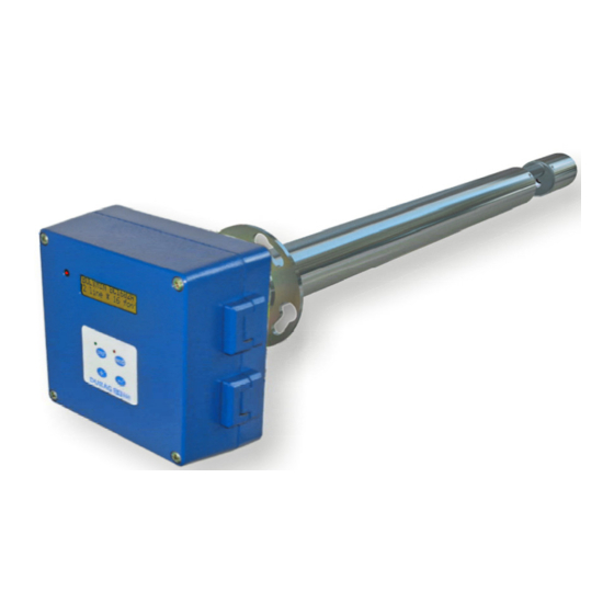
DURAG D-R 800 Manual (154 pages)
Dust concentration meter
Brand:
DURAG
| Category:
Measuring Instruments
| Size: 8 MB
Table of Contents
Figures
5
Table of Contents
5
Figure 4.1: Position of the Rating Plates
35
Figure 4.2: Supply Unit (Above) (Measurement) Probe (Below)
37
Figure 4.3: Vertical Measuring Probe for Vertical Ducts
38
Figure 4.4: Horizontal Measuring Probe for Horizontal Ducts
38
Section 2
39
Figure 5.1: Components of the D−R 800
41
Layout and Function
41
Functional Description of the System Components
41
Figure 5.2: Functional Diagram I
42
Figure 5.3: Functional Diagram II
42
Functional Diagram
42
Figure 5.4: Layout of the Supply Unit
43
Supply Unit
43
Layout of the Supply Unit
43
Purge Air Heater (Optional)
44
Purge Air Monitoring (Optional)
44
Section 3
45
Configuration, Installation, Commissioning
47
D−R
47
Safety
47
Installation
48
Preconditions for Use
48
Table 6.1: Checklist: Preconditions for the Operation of the D−R 800
49
Figure 6.1: Selection of the Correct Flange / Lance Length
50
Table 6.2: Selection of the Correct Flange / Lance Length
50
Figure 6.2: Dimensionaldrawing (Measuring )Probe
51
Transport
51
Installation Location, Place of Use
51
Figure 6.3: Installation Point of the Probe; Upstream Section
52
Figure 6.4: Installation Point of the Probe; Shortened Upstream Section
52
Figure 6.5: Welding-In Drawing D−R 800 for a Horizontal Duct
53
Figure 6.6: Welding-In Drawing D−R 800 for a Vertical Duct
53
Installation
53
Weldingin the Flange
53
Figure 6.7: Dimensional Drawing for the Supply Unit D−R 800
54
Connection Power Supply, Operating Media
54
Figure 6.8: Changing the Fuse in the Supply Unit D−R 800
55
Figure 6.9: Wiring Diagram of the Supply Unit D−R 800
56
Table 6.3: Terminal Assignment
57
Figure 6.10: Purge Air Connection Supply Unit
58
Figure 6.11: Purge Air Connection Measurement Unit
59
Table 6.4: Selection of the Purge Air Restrictor
59
Commissioning
61
Measures before Initial Commissioning
61
Figure 6.12: Diaphragm Openings
62
Figure 6.13: Miniature Fuse Holder
62
Commissioning
62
Figure 6.14: Evaluation Unit with Display and Controls
63
Table 6.5: Checklist: Preconditions for Commissioning the D−R 800
61
Section 4
65
Figure 7.1: Installation of the Purge Air Heating I
67
Installation and Adjustment of the (Optional) Purge Air Heating (SLH)
67
Optional Accessories, Installation and Use
67
Purge Air Heating
67
Figure 7.2: Installation of the Purge Air Heating II
68
Figure 7.3: Installation of the Purge Air Heating III (Electrical Connection)
69
Figure 7.4: Purge Air Heater Internal Control Loop
70
Figure 7.5: (Optional) Weather Protection Hood Purge Air Heater
71
Figure 7.6: Installation of the Purge Air Heater IV (Weather Protection Hood, Optional)
71
Figure 7.7: Adjustment of the Purge Air Heater I
72
Figure 7.8: Adjustment of the Purge Air Heater II
72
Figure 7.9: Dimensional Drawing of the Purge Air Heater
73
Figure 7.10: Connection of the Purge Air Monitoring Unit
74
Installation and Adjustment of the (Optional) Purge Air Monitoring
74
Figure 7.11: Local Adjustment of the Purge Air Monitoring
75
Table 7.1: LED Display for the Purge Air Monitoring Unit
75
Table 7.2: Possible Causes / Remedies for "Error During Device Adjustment
76
Dimensional Drawing Rate of the Flow / Temperature Monitor for Purge Air
78
Figure 7.12: Dimensional Drawing Rate of the Flow / Temperature Monitor
78
Weather Protection Hood
79
Dimensional Drawing of the Weather Protection Hood
79
Dimensional Drawing for the Weather Protection Hood for Purge Air Heater
80
General Information on the Modbus Protocol
81
Technische Beschreibung DURAG Modbus für D−R
81
Type of Cabling, Cross-Section, Max. Length of the Modbus Cables Used
82
Table 7.3: Teminal Assignment for Modbus
83
Terminating Resistor for Modbus
83
Table 7.4: Abbreviations and Terms in the Tables
85
Modbus Register Definitions
85
Table 7.5: Data Formats in the Tables
86
Table 7.6: Unsupported Function Codes
86
General Parameters and Functions
87
Table 7.7: General Parameters and Functions
90
Table 7.8: Status Codes
91
Table 7.9: D−R 800 Messages
92
D−R 800 Messages
92
Table 7.10: D−R 800 Parameters and Functions
93
Table 8.1: Value Pairs Table from Gravimetric Comparison Measurement
114
Table 8.2: Value Pairs Table for the Calibration Function
115
Table 8.3: Table for Documentation of the Calibration as It Is Being Performed
117
Table 9.1: Messages from the Measuring Unit
126
Table 9.2: Messages from the Measuring Unit (Causes and Remedies)
128
Table 10.1: Overview of Control Parameters for Code Level 1
135
Advertisement
Advertisement
Related Products
DURAG D-R 220
DURAG D-LX 201
DURAG D-LX 721
DURAG D-R 820 F
DURAG D-R 290
DURAG D-FL 200
DURAG D-ISC 100 2 Series
DURAG D-ISC 100 R 2
DURAG D-LX 100 All-In-One
DURAG 4 019 962
DURAG Categories
Measuring Instruments
Monitor
Scanner
Control Unit
Industrial Electrical
More DURAG Manuals
Login
Sign In
OR
Sign in with Facebook
Sign in with Google
Upload manual
Upload from disk
Upload from URL