
Related Manuals for DURAG D-R 220


Summary of Contents for DURAG D-R 220
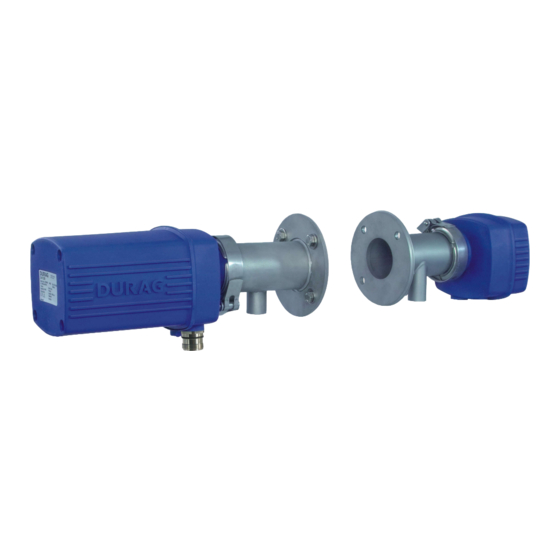
- Page 1 D-R 220 Dust Concentration and Opacity Monitor Before starting any work please read the operating manual! Article no.: GmbH • Kollaustraße 105 • 22453 Hamburg • Germany • www.durag.com 4 013 096...
- Page 2 Operating manual Dust concentration and opacity monitor D-R 220 Version: 10011800-11-03 Previous version: 10011800-10-02 Production date: 22/01/2021 Document scope: DURAG GmbH Telephone: +49 (40) 55 42 18 – 0 Kollaustraße 105 Fax: +49 (40) 58 41 54 22453 Hamburg Email: info@durag.com...
-
Page 3: Table Of Contents
6.3.2 Settings via DIP switch (alternative)....................38 Linearity check (software check)..................... 39 Firmware Update..........................42 Replacing the battery in the measuring head.................. 43 Decommissioning, storage Decommissioning..........................44 Storage............................44 Messages/error elimination Information............................45 Warnings............................46 Simple error............................. 47 D-R 220... - Page 4 Setting the measuring head to a zero point reflector............... 66 11.1.5 Setting the zero point reflector to a measuring head............... 67 11.1.6 Commissioning without a zero tube....................68 11.1.7 Adjusting the light intensity via DIP switch..................70 11.1.8 Linearity check (ammeter check)..................... 71 Index D-R 220...
-
Page 5: Information On This Manual
Information on this manual This manual is aimed at qualified specialist personnel. Additional descriptions that may be relevant for setup and operation of the D-R 220 measuring system (depending on the associated components) are described in the relevant operation manuals for these components, e.g.: D-TB x00 Terminal–Box... - Page 6 Risk of injury due to wrong spare parts! Incorrect or defective spare parts can result in damage or malfunctions and may also impair safety. ▶ Only use original spare parts of the manufacturer. ▶ Procure spare parts through authorised dealers or directly from the manufacturer. D-R 220...
-
Page 7: Safety
Personnel, qualifications The manual is intended for qualified specialist personnel: Work on the D-R 220 must only be carried out by the following personnel: Specialised personnel are those who because of their specialist training, knowl ●... -
Page 8: Intended Use
2 | Safety Electrical connection The D-R 220 is supplied with a plug connector for the supply voltage and data connec tion. in the measuring head is 24 V , The maximum supply voltage for the voltage present at the customer's relay outputs (max. 60 V /30 V~), see Technical data [} 54]. -
Page 9: Product Description
3 | Product description Product description The Dust concentration and opacity monitor D-R 220 works based on the transmission principle. This means that the light from an LED emitted by the measuring head pass es through the measurement path and is thrown back by a reflector. The attenuation of the light beam caused by the dust contents in the measurement path is detected by a high-sensitivity detector, and evaluated by the electronic equipment. - Page 10 3 | Product description Name • Function D-R 220 M • Measuring head with purge flange D-R 220 R • Reflector with purge flange Welded-in pipe with adjustment flange and seal • Process connection The following is required for connections and supply: D-TB 200 terminal box •...
-
Page 11: Variants, Design Types
(measuring head) Board no. 20 Device connection (plug) from the terminal box (housing hood not shown) Terminal strip X9 (Illustrations may differ from the actual appearance.) Fig. 3.1: D-R 220 measuring head part 1 D-R 220... - Page 12 LEDs (equalisation to dust-free connection for purge flange measurement path, messages) (measuring head) Board no. 20 Sighting mechanism Housing hood not shown Jumper X6 (termination RS485) (Illustrations may differ from the actual appearance.) Fig. 3.2: D-R 220 measuring head part 2 D-R 220...
- Page 13 W but view (only for R1) of reflective layer (Illustrations may differ from the actual appearance.) Fig. 3.3: D-R 220 Reflector part 1 Purge flange Purge air connection Quick-release clamp Housing base with process connection for...
-
Page 14: Maximum Tube Lengths With D−R 220 Adjustment Flanges
LED. If the light cone touches the ends of the tube, this will cause reflec tions that will distort the measurement result. Fig. 3.5: D-R 220 Welded-in pipe with adjustment flange This table shows the maximum tube lengths up to which measurement can be per... -
Page 15: Zero Point Reflector
A dust-free measurement path is required to set up the measuring head. This can be ordered from DURAG as a special accessory, and consists of a tube with darkened interior and with flanges on both ends, into which an aperture has been in... -
Page 16: Meaning Of The Display Leds
Fig. 3.7: Dust-free measurement path Meaning of the display LEDs In the housing cover of the D-R 220 is an inspection window for the sighting mecha nism, which can also be used to view the 4 display LEDs. The LEDs indicate different system states during normal operation. - Page 17 Flashing alternately green (4) Faulty Modbus frame LED off Normal operation Flickering Normal operation: DURAG Modbus active Flashing alternately red (3), Faulty Modbus frame (see above) LED off Data interface not active 1 green - 2 yellow - 3 red - 4 green Table 3.7: Meaning of the LEDs and their flash codes...
-
Page 18: Installation
2 Welded-in pipe with adjustment flange 3 Anchor plate 4 Gusset plate 5 Flexible sealant 6 Temporary movements of the welded-in pipe Before creating an opening, check that there are no harmful gases, high tempera tures or high pressures in the channel/stack. D-R 220... - Page 19 [} 18] D), firstly create an open ing in the stack's outer wall. For installation in the inner wall, this opening should be somewhat larger. Create an appropriate opening in the inner wall. The procedure depends on the D-R 220...
- Page 20 3.4 Maximum tube lengths with D−R 220 adjust ment flanges [} 14]). This is calculated from the length of the welded-in pipe minus the insertion depth into the stack/channel (>30 mm) and the distance between the flange and the outside of the stack/channel. D-R 220...
-
Page 21: Installation Of The Measuring Head And Reflector
Measuring head Reflector Purge flange Threaded studs onto which the Disc springs measuring head or reflector is ad Spherical washer justed and attached onto the adjust adjustment flange ment flange. Purge flange Fig. 4.2: Installation onto the adjustment flange D-R 220... - Page 22 Use a connecting cable with plug connection to connect the measuring head and the terminal box (with blower) or the terminal box (without blower).** Purge flange Purge flange/housing base connection a1 Quick-release clamp b1 Housing base Fig. 4.3: Attaching to the purge flange with a quick-release clamp D-R 220...
-
Page 23: Adjusting The Purge Flange On The Reflector
Even a small deviation from the measuring path length used for the zero tube equali sation will influence the measuring value, particularly with short distances. The mea suring path length may also change depending on how tightly the nuts on the disc springs have been tightened. D-R 220... -
Page 24: Adjusting The Purge Flange On The Measuring Head
Correct setting: Correct setting: view when using an R2 reflector view when using an R1 reflector Incorrect setting: Incorrect setting: view when using an R2 reflector view when using an R1 reflector Fig. 4.7: Aligning the measuring head D-R 220... - Page 25 A ‑ B and the spot of light in the adjustment device moves in a verti cal direction. Once the adjustment work has been carried out, the Dust concentration and opaci ty monitor is ready for operation. D-R 220...
-
Page 26: Configuration And Commissioning
5 | Configuration and commissioning Configuration and commissioning Certain parameters need to be entered before the D-R 220 can be used. The measur ing device can be fully configured using software. Alternatively, the most important settings can also be made using DIP switches on the main board of the measuring head. - Page 27 Make sure that the two parts of the housing are lying perfectly on top of one another on the seal. Ø 25 mm Ø 15 mm b Reflector insert with d Active aperture f Available aperture(s) in reflector R1 storage position Table 5.2: Reflector apertures D-R 220...
-
Page 28: Setting Made Via Software (Recommended)
Insert a mini-B-type 5-pin connector into the USB port on the bottom of the housing of the D-R 220 , and insert the other connector into a free USB port on the PC. When using the USB port, only the currently connected device will be displayed in the software's device list;... - Page 29 ON position, then the corresponding parameters cannot be adjus ted using the software. The positions of the S1 switches can be displayed in the D‑ESI 100: Sitemap > »Device (e.g. D-R 220 ) > > Specific parameter > Device con...
-
Page 30: Equalisation To The Dust-Free Measurement Path (Zero Tube)
[} 28] 5.2.2 Equalisation to the dust-free measurement path (zero tube) For the precise adjustment of the D-R 220 measuring system to the existing measur ing path length, a defined, dust-free measurement path is used (as described in sec tion 3.7 Measurement tube for a dust-free measurement path [}... -
Page 31: Setting The Measuring Head To A Zero Point Reflector
5.2.2 Equalisation to the dust-free measurement path (zero tube) [} 30] 11.1.3 Equalisation to the dust-free measurement path (via button S2) 64]) ü The measuring head is disassembled from the channel/stack. We recommend switching off the measuring device. D-R 220... - Page 32 (see Figure on the left). Fig. 5.10: Serial number of the zero point reflector Sitemap > »Device (e.g. D-R 220 ) > > Specific parameter > Device con...
-
Page 33: Commissioning Without A Zero Tube
If no dust-free measuring-path (zero tube) is available, it is possible to carry out a rough equalisation of the system. The measuring head and reflector can be already attached at the actual measuring location here. Sitemap > »Device (z.B. D-R 220 ) > > Specific parameter > Calibra... - Page 34 5 | Configuration and commissioning Distance [m] Fig. 5.13: Setting the light intensity depending on the measurement distance Setting Sitemap > »Device (e.g. D-R 220 ) > > Specific parameter > Device con figuration > Device parameter >ZPR: LED current adjustment [mA] >...
-
Page 35: Setting Via Dip Switch (Alternative)
[} 63]. Individual device features cannot be used without using software (D−ESI 100, D−ISC 100). The corresponding settings are therefore only described in section 5.2 Setting made via software (recommended) [} 28]. D-R 220... -
Page 36: Maintenance
6 | Maintenance Maintenance The D-R 220 is a measuring system with maintenance intervals that depend on the in stalled system and that must be defined by the facility operator. The maintenance in tervals depend on: The type, composition and properties of the measured medium ●... -
Page 37: Cleaning The Optical Surfaces (Measuring Head And Reflector)
During operation, instead of the purge flange, the zero point reflector adjusted to the measuring head * (D-R 220 N) should be fitted onto the measuring head with the quick-release clamp. * Compare the serial number on the type plate for the zero point reflector and the serial number entered when carrying out the measuring head settings e.g. -
Page 38: Settings Via Dip Switch (Alternative)
ü The measuring head is disassembled from the channel/stack, and the plug con nector for the measuring head connections is disconnected. Instead of the purge flange, the supplied zero point reflector * (D-R 220 N) should be fitted onto the measuring head with the quick-release clamp, while the device is operational. -
Page 39: Linearity Check (Software Check)
The serial number is displayed as shown in the following Figures: Fig. 6.7: Serial number of the zero point reflector Sitemap > »Device (e.g. D-R 220 ) > > Specific parameter > Device con figuration > Zero point reflector (ZPR) > ZPR: Serial number >... - Page 40 37]). Fig. 6.9: Test filter in the zero point reflector Instead of the purge flange, the supplied zero point reflector D-R 220, should be fitted onto the measuring head with the quick-release clamp, while the device is operational. Make sure that the pins on the housing base are inserted into the corresponding openings (seeFig.
- Page 41 Repeat the measurement if necessary with the different test filters (optional acces sories), and make a note of the results. Fig. 6.11: Test filter type plate Sitemap > »Device (z.B. D-R 220 ) > > Specific parameter > Calibra tion > Device calibration > Path length correction factor(PLCF)
-
Page 42: Firmware Update
Wherever possible, allow components to cool down to ambient temperature before starting work. ü It is not essential to remove the D-R 220 from the output channel in order to carry out a firmware update. When the purge air supply is running, the housing can be... -
Page 43: Replacing The Battery In The Measuring Head
Wherever possible, allow components to cool down to ambient temperature before starting work. ü It is not essential to remove the D-R 220 from the output channel in order to change the battery. When the purge air supply is running, the housing can be opened, taking into account the necessary safety measures (see section 2.3 Basic... -
Page 44: Decommissioning, Storage
7 | Decommissioning, storage Decommissioning, storage Decommissioning The D-R 220 must be decommissioned: Immediately in the event of a purge air failure (disassemble the measuring head ● and reflector from the measurement channel) If the system is shut down for a longer period of time (> 1 week) ●... -
Page 45: Messages/Error Elimination
8 | Messages/error elimination Messages/error elimination Messages output and saved by the DURAG Bus devices are divided into four catego ries: Information Information messages serve to inform. They notify the user of work that deviates from the normal measuring operation. -
Page 46: Warnings
No action necessary ● [023] Device in maintenance mode System is in maintenance mode No action necessary ● Table 8.1: List of information D-R 220 Warnings Warning Cause; by whom Status (●) Available actions [064] Measuring value 1:... -
Page 47: Simple Error
Reduce the light intensity (see Section 5.2.5 Ad ● justing the light intensity [} 33] (with D‑ESI 100) 11.1.7 Adjusting the light intensity via DIP switch [} 70]. Table 8.3: List of simple faults for the D-R 220 D-R 220... -
Page 48: Critical Error
If this is not detected, then this error message appears. The reasons may be: Analogue printed circuit board D-R 220 no. 10 de fective. Transmitting LED defective. Stepper motor for comparison aperture defective. -
Page 49: Parameters, Factory Settings, Functions
The information in the Value columns of the following tables indicates the factory set tings (default). The designation (terminology) and order of the information are based on the structure of the DURAG Engineering and Service Interface D-ESI 100. Common parameter Parameter... - Page 50 Relay setup ● Relay 1 setup 0x00000010 Assignment of relay 1 to different messages 0x00000010 = measuring device: Fault (F) Relay 2 setup 0x00000020 Assignment of relay 2 to different messages 0x00000020 = measuring device: Maintenance/ check function (C) D-R 220...
-
Page 51: Specific Parameter
Calibration Device calibration ● Path length correction factor (PLCF) / Stack 1,000 Path length correction factor for calculating opaci factor ty at the stack aperture Flange to flange distance (LFF) [mm] 2,500 Flange to flange distance in mm D-R 220... -
Page 52: Functions
0 = inactive Enter / exit fixed output mode Measuring value 2: 0.0000 Enter / exit fixed output mode Measuring value 3: 0.0000 Enter / exit fixed output mode Measuring value 4: 0.0000 Enter / exit fixed output mode D-R 220... - Page 53 0. The measurement will go on until it be comes stable (parameter changes to 1 and the measurement stops automatically), or until it is stopped by the user with the parameter 'Stop dust-free path measurement'. Table 9.3: Functions D-R 220...
-
Page 54: Technical Data
● D-R 220 N zero point reflector ● D-TB 200 terminal box (option) ● D-R 220 E adjustment flange with tube (2 pcs, option) ● D-ISC 100 universal operating unit (option) ● Table 10.2: Technical data - general D-R 220 M measuring head... - Page 55 10 | Technical data D-R 220 M measuring head Lowest detection limit 0.2% CR (Certification Range) Combined standard uncertainty 0.015 OD in the range 0 ... 0.2 OD to EN 14181 Light source Process connection With purge flange on adjustment flange, pitch circle 100 mm,...
-
Page 56: Dimensioned Drawings
10 | Technical data D-R 220 purge air tube Purge air tube Ø 25 mm Purge air tube D-RX 250 Y distributor (1 pc), connection of terminal box D−TB 200 with D-R hose clamp 24 ... 28 mm (6 pcs) -
Page 63: Appendix
11.1 Measuring device settings via DIP switch (alternative) The D-R 220 is usually parameterised using D‑ESI 100 (operating software). To adjust the settings without this operating software, there is the option of using a DIP switch, a button and LEDs in the measuring head. -
Page 64: Limit Values
50% opacity. If "Extinction 0.4" has been selected, the limit value will be 0.2. 11.1.3 Equalisation to the dust-free measurement path (via button S2) For the precise adjustment of the D-R 220 measuring system to the existing measur ing path length, a defined, dust-free measurement path is used (as described in sec tion 3.7 Measurement tube for a dust-free measurement path [}... - Page 65 LED goes out). Equalisation can then be restarted again. ✓ When the push button S2 is actuated as described above, and the resulting measuring value analysis is initiated, the yellow LED (LED Y) starts to flash. D-R 220...
-
Page 66: Setting The Measuring Head To A Zero Point Reflector
Make sure that the pins on the housing base of the measuring head are inser ted into the corresponding openings on the zero point reflector (see Figure). This is the only way of ensuring a perfect connection of the two devices. D-R 220... -
Page 67: Setting The Zero Point Reflector To A Measuring Head
Following equalisation, all of the measuring heads set to this zero point reflector will need to be re-calibrated (see Section 11.1.4 Setting the measuring head to a zero point reflector [} 66]). Equalisation is performed by following the steps below: D-R 220... -
Page 68: Commissioning Without A Zero Tube
ü The measuring head is disassembled from the channel/stack. The measuring de vice is in operation. Instead of the purge flange, the zero point reflector (D-R 220 N) should now be fitted onto the measuring head with the quick-release clamp while the D-R 220 is in operation. - Page 69 The push button must be released on the 4th flashas otherwise equalisation will be terminated (Escape). ✓ If equalisation was not started successfully, e.g. if the button was pressed for too long or too short a period, the procedure can be repeated easily (by press ing push button S1). D-R 220...
-
Page 70: Adjusting The Light Intensity Via Dip Switch
5.2.5 Adjusting the light intensity [} 33] and the diagram Fig. 5.13 If the transmitting LED is too bright, the red LED will signal an overload on the board. The LED current can then be reduced via switches S1:1 and S1:2 (see page 63]). D-R 220... -
Page 71: Linearity Check (Ammeter Check)
ü Before opening the measuring head, firstly make sure that the ESD protective measures are in place. Instead of the purge flange, fit the zero point reflector * (D-R 220 N) onto the mea suring head with the quick-release clamp. Do not switch off the D-R 220. - Page 72 [mA] output range* Example: The filter with the type plate shown above is used. The D-R 220 is set to 50% opacity*. A value of 5.9 mA is measured. The converted measuring value is determined using Eq. 11: 15,9 mA −...
- Page 73 Switch arrangement on the board 29, 63 Risk of property/ environmental damage - note 5 Tips, recommendations Information (list) Transmitting LED LED G 66, 70 Visual inspection LED Y 65, 69 LEDs, Bedeutung der Light intensity Limit values Linearity check, evaluation D-R 220...
- Page 74 Warnings (list) Warnings, list Wartung Arbeiten, nicht zulässige 12, 30, 64 Zero point 40, 71 Zero point reflector 15, 37, 38, 40, 71 Zero point reflector, setting to the measuring head 31, 66 Zero tube equalisation 30, 64 D-R 220...
- Page 75 12 Index D-R 220...
- Page 76 GmbH • Kollaustraße 105 • 22453 Hamburg • Germany • www.durag.com...
Need help?
Do you have a question about the D-R 220 and is the answer not in the manual?
Questions and answers