Table of Contents
Advertisement
Quick Links
Advertisement
Table of Contents
Troubleshooting

Related Manuals for Timpte Tender


Summary of Contents for Timpte Tender
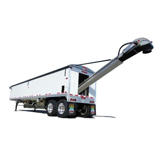
- Page 1 TIMPTE Bulk Commodity Trailer with Combo Tender Option OPERATOR’S MANUAL Serving the transportation industry since 1884. TIMPTE, INC. 1827 Industrial Drive David City, NE 68632 402-367-3056 011-51837 September 2019 TenderCov19.indd 1 8/30/2019 10:10:25 AM...
- Page 2 If you believe that this vehicle contains a safety defect you may contact Timpte Trailer The trailer was designed and inspected to conform to industry standards and all applicable NHTSA safety standards. Timpte Trailer Co. warrants this vehicle to be free from defects in materials and workmanship when manufactured per the limited warranty agreement.
-
Page 3: Table Of Contents
TRACTOR PTO SYSTEM “WET KIT” SPECIFICATIONS ................................28 TENDER HYDRAULIC SYSTEM MAINTENANCE ..................................28 TIMPE TENDER TRAILER HYDRAULIC SCHEMATIC 577-60478 ..............................29 SELF-CONTAINED TIMPTE TENDER TRAILER HYDRAULIC SCHEMATIC 577-60429 ....................... 31 TENDER HYDRAULIC TESTING PROCEDURE .................................... 33 CONVEYOR BELT TENSION AND TRACKING ....................................39 CONVEYOR BELT TRACKING ADJUSTMENT .................................... - Page 4 Changes are continually being made to improve our product lines. We want to thank you for purchasing a Timpte tender trailer and to let you know that it was built for long life and low cost of operation. However, regular and proper maintenance of the trailer and your common sense use of it are required to extend the life of the trailer.
-
Page 5: Normal Trailer Operation
(a) concentrated loads; (b) loads in excess of the Gross Axle Weight Rating (GAWR) or Gross Vehicle Weight Rating (GVWR) stated on the Certification Plate affixed to the trailer by Timpte; and (c) accidental damage, or (d) stresses, impacts or shocks greater than those commensurate with normal, reasonable lawful use. -
Page 6: Safety
The following section contains safety warnings and operational directions. Some of these are used as decals on the Timpte Tender Trailers. Due to differences in configurations and equipment, your trailer may or may not use all the decals and emblems shown. Newer trailers may also have decals and emblems that differ from older trailers. - Page 7 WARNING THIS TRAILER IS EQUIPPED WITH TRAILING BEAM AIR RIDE SUSPENSION. 1. MANUALLY EXHAUST ALL AIR IN THE SUSPENSION SYSTEM PRIOR TO SUPPORTING A LOADED TRAILER ON THE SUPPORT LEGS. FAILURE TO COMPLY CAN CAUSE STRUCTURAL DAMAGE TO THE SUPPORT LEG BRACES.
-
Page 8: Decals & Warnings
CAUTION NEW FMVSS-121 REGULATIONS MANDATE HIGHER PRES- SURE LEVELS IN THE SUPPLY LINE. TRAILER BRAKE PERFORMANCE WILL BE IMPAIRED IF TRACTOR COMPRESSOR ADJUSTMENT IS TOO LOW. CHECK YOUR TRACTOR! COMPRESSOR CUT-IN PRESSURE, ADJUST TO 105 PSI CUT-IN GOVERNOR P/N 035-29182 CAUTION DO NOT ATTEMPT TO HOIST TRAILER... - Page 9 Updated – 02/03/20 Date of Origin – 02/24/11...
-
Page 10: Air Brake System
AIR BRAKE SYSTEM Your new Timpte trailer is equipped with an air brake system which meets or exceeds the requirements of the federal regulation FMVSS-121 for grade-holding ability and emergency stopping in the event of an air supply failure in the service brake system. -
Page 11: Abs Braking System
BACKUP WARNING SYSTEM A backup warning system consisting of an audible alarm is available as an option on your Timpte Bulk Commodity trailer. The system is intended to indicate that the vehicle is backing up. -
Page 12: Control Of Safe Operation
You, the operator, have the Greatest Control over Safe Operation. 1. You, the operator, have control of the most important factors that affect safe trailer operation and vehicle stability. Trailers are a tool and, like any tool, are safe only when properly used by a conscientious, trained and qualified operator. -
Page 13: Trailer Kingpin Wear
Per Recommended SAE Standards, check King Pin for wear across the pin neck and also the pin shoulder. In accordance with industry standards, Timpte recommends that the kingpin and its mounting structure be inspected for wear and damage on a daily basis. -
Page 14: Inspection Procedures Before Each Trip
(CFR Sections by Citation). Failure to regularly inspect the trailer may also void the warranty. While it is ultimately the operator’s responsibility to properly perform and document the pre-trip inspection, Timpte provides the following recommendations and suggestions. -
Page 15: Lights And Reflectors
CAUTION! Plastic King Pin Liners (Lube Plate) cannot be installed onto Timpte Trailer upper cou- pler/king pin assemblies unless the trailer was purchased with that specification. A lube plate changes the king pin interface dimensions relative to the fifth wheel lock. -
Page 16: Wheels And Rims
WHEELS AND RIMS Check all wheel nuts for tightness. Wheel flange nuts should be torqued to 450 to 500 ft. lbs (dry). Check all metal surfaces thoroughly while making tire inspections and during tire changes. Look for: • Excessive rust or corrosion build-up •... -
Page 17: Side Structures
SIDE STRUCTURES Check the trailer sides for inconspicuous damage to the top and bottom rails as well as the side structure – cracks, contusions, sharp bends, ripples, or missing fasteners. Any problems observed in the side structure should be correct- ed immediately to prevent the damage from extending further. -
Page 18: Operating Instructions
OPERATING INSTRUCTIONS PARKING/EMERGENCY BRAKING SYSTEM This portion of the air brake system makes provision for parking a vehicle on a grade and for emergency stopping in the event of a failure of air supply in the service brake system. Air pressure within the parking brake chamber is required to release the spring brake. An air reservoir is provided to store enough air to release the brakes at least once by means of the tractor parking brake control, if there is an air line failure. -
Page 19: Operating Your Timpte Tender
OPERATING YOUR TIMPTE TENDER WARNING AT NO TIME SHALL YOU TRY TO DISLODGE COMMODITY IN THE CONVEYOR WHILE THE SYSTEM IS OPERATING! DO NOT CHECK FOR OIL LEAKS WITH YOUR HANDS. NEVER WALK UNDER THE INCLINED CONVEYOR!! KEEP AWAY FROM OVERHEAD POWER LINES OR OTHER OBSTRUCTIONS WITH THE INCLINED CON- VEYOR. -
Page 20: Trailer Unloading
Note: Timpte Trailers are designed to transport free flowing commodity. Knock rails and pneumatic (air) hammer (vibra- tor) options are available to be installed to assist with the unloading of commodity, if needed. Speak with a Timpte Sales Representative with any questions you may have with respect to knock rails and pneumatic (air) hammer options. -
Page 21: Self-Contained Power Unit Operation
SELF-CONTAINED POWER UNIT OPERATION • At the rear of the trailer, locate the control panel for the self-contained power unit. o It is located on the road side of the trailer in the back above the trailer bogie. • Verify that the hydraulic quick couplers on the self-contained power unit are fully engage with the appropriate hoses. -
Page 22: Thunder Electric Tarp System
PROGRAMMING REMOTE TO WORK WITH THE THUNDER ELECTRIC TARP SYSTEM 1. Power on the keypad controller on the front of the trailer by holding the “Open” and “Close” buttons on the keypad simultaneously for 5 seconds or until the white light illuminates to indicate the system is active. 2. -
Page 23: Programming Remote To Work With The Ez Flow Trap System
PROGRAMMING REMOTE TO WORK WITH THE EZ FLOW TRAP SYSTEM 1. Power on the keypad controller on the trailer by holding the “FRONT OPEN” and “FRONT CLOSE” buttons on the keypad simultaneously for 3-5 seconds or until the blue light illuminates to indicate the system is activated. -
Page 24: Thunder Electric Tarp System, Manual Operation
THUNDER ELECTRIC TARP SYSTEM, MANUAL OPERATION 1. Remove the motor shaft drive nut and bolt assembly from the roll tube axle. See figure 5.1. Note: Save the nut and bolt. If drive bolt will not come out due to excess tension from the drive motor, disconnect the motor leads and use jumper cables from a battery source to drive the motor in a direction that removes... -
Page 25: Troubleshooting Guide
THUNDER TARP TROUBLESHOOTING GUIDE Remote function not working. 1. Reset system by removing power trailer power connection for 15 seconds then reconnect. 2. Turn on the tarp system by pressing the (Open) & (Close) buttons simultaneously on the keypad for 3-5 seconds until the LED and buttons illuminate. - Page 26 d) Seven flashes indicates there is not enough amperage or voltage to run the motor OR the drive motor windings are shorted. MAY REQUIRE REMOVING POWER TO RESET. (1) Connect an alternate power source to verify a low amperage/voltage problem. (2) Make sure the battery is fully charged and the charging system on the truck or power supply is running and working properly.
-
Page 27: Ez-Flow Hydraulic Door Troubleshooting Guide
EZ-FLOW HYDRAULIC DOOR TROUBLE SHOOTING GUIDELINES Updated – 02/03/20 Date of Origin – 02/24/11... -
Page 28: Pressure Relief Adjustment
PRESSURE RELIEF ADJUSTMENT The hydraulic power supply pump is equipped with two pressure relief valves to maximum system pressure at a safe level. These relief valves are located on each side of the pump, 180 degrees from each other. At the hose connections the ports on side of the pump are marked with “C1”... -
Page 29: Ez-Flow Quick Release System
EZ-FLOW QUICK RELEASE SYSTEM Quick Release Operations 1. Release pressure at poppet valve per decal (shown above) 2. Remove spring from pin (unlatch pin retainer) 3. Remove pin from clevis and free door brackets from cylinder 4. Open trap door with emergency opener system Updated –... -
Page 30: Tractor Pto System "Wet Kit" Specifications
Wing Coupler, 1” Male - 029-57862 Wing Coupler, 1” Female - 029-57863 TENDER HYDRAULIC SYSTEM MAINTENACE It is important that the system has clean filtered oil. Make sure the system has a filter in the pressure line. Change this element after the first 40 hours of use and then a minimum of semi-annually thereafter. -
Page 31: Timpe Tender Trailer Hydraulic Schematic 577-60478
TIMPTE TENDER TRAILER HYDRAULIC SCHEMATIC 577-60478 Updated – 02/03/20 Date of Origin – 02/24/11... - Page 32 Updated – 02/03/20 Date of Origin – 02/24/11...
-
Page 33: Self-Contained Timpte Tender Trailer Hydraulic Schematic 577-60429
SELF-CONTAINED TIMPTE TENDER TRAILER HYDRAULIC SCHEMATIC 577-60429 Updated – 02/03/20 Date of Origin – 02/24/11... - Page 34 Updated – 02/03/20 Date of Origin – 02/24/11...
-
Page 35: Tender Hydraulic Testing Procedure
TENDER HYDRAULIC TESTING PROCEDURE EQUIPMENT: One Flow Meter Assembly with 1-Inch Quick Disconnects Four tee fittings with pressure gauges: Two each ½-inch JIC Tee for horizontal/lower conveyor Two each ¾-inch JIC Tee for incline/upper conveyor ONE EACH OPEN END WRENCH:... - Page 36 2. Repeat procedure for horizontal conveyor pressure line. Pressure hose is connected to the bottom port of the hydraulic motor to the lower stainless steel tubing on the horizontal conveyor. See Photo below for gauge position. Test Gauges – Incline/Upper Conveyor 1.
- Page 37 Flow Meter Assembly Installation 1. Install Flow Meter Assembly in pressure line at the nose of trailer by pulling collar on female disconnect back and pushing female disconnect on to male coupler on the nose of the trailer. Release collar and pull on flow meter assembly to insure the quick disconnects are connected. 2.
- Page 38 TEST PROCEDURE: CAUTION: To test conveyor system, power unit must be equipped with pressure relief valve set below 3000 psi before proceeding. Power Unit Relief Check: 1. Insure needle valve on Flow Meter Assembly is in open position by turning the needle valve counter clockwise.
- Page 39 Repeat this step until the relief is set at 2500 psi. Setting relief pressure on selector valve. Loosen the adjustment setscrew jam nut on relief valve using a 9/16-inch wrench. Use a 3/16-inch hex wrench and turn relief clockwise to increase pressure and counter clockwise to decrease pressure.
- Page 40 11. Reverse conveyor by moving hydraulic selector valve outward. This will reverse the lower conveyor and incline conveyor. 12. Verify pressure at each gauge. Pressure at lower conveyor return line which now is the pressure line should read between 500 to 1000 psi. b.
-
Page 41: Conveyor Belt Tension And Tracking
CONVEYOR BELT TENSION AND TRACKING To drive the conveyor belt without slippage and to track it in a proper way, a certain belt tension is necessary. The tension applied has to be such that there is no slippage on the driving drum when the belt is started at full load. -
Page 42: Conveyor Belt Tracking Adjustment
CONVEYOR BELT TRACKING ADJUSTMENT: Both the Inclined and Lower Conveyors have Belt Tracking adjustment mechanisms as part of the conveyor assemblies To adjust belt tracking (belt centering on the conveyor) : • Loosen the tracking mechanism lock nuts (inside nuts) to allow belt tracking adjustment (forward or backward) •... -
Page 43: General Maintenance
Various chemicals can cause severe corrosive damage to your aluminum grain trailer. To prevent severe damage to your trailer due to corrosion, contact Timpte Trailer Company Product Engineering to verify that the materials you are hauling are compatible with the materials used in the construction of the trailer. -
Page 44: Air Hammer (Vibrator) Maintenance
AIR HAMMER (VIBRATOR) MAINTENANCE The air hammer employed to help dislodge commodity should be lubricated on a regular basis. The air hammer man- ufacturer recommends a SAE 10 or lighter oil for this purpose. Frequency of lubrication is directly related to volume of usage. - Page 45 CLEAR PLASTIC NIPPLE WITH GOLD ADJUSTMENT SCREW SETTING THE OIL AMOUNT • Set the oil amount using the metering screw on the standard oil-mist lubricator’s drop attachment. • Determine amounts of oil discharged by observing the number of drops in the drop attachment. Standard value: 1-2 drops/min (qv = 1000 NI/min) OILER SECTION ONLY SHOWN TROUBLE-SHOOTING:...
-
Page 46: Hub Maintenance
This step will minimize the possibility of dirt and road grime entering the system. Wheel end-play is recommended to be confirmed annually (mininum) for all axle wheel-ends to improve wheel bearing life. Timpte recom- mends wheel-end play inspections every 100,000 miles of trailer use to properly maintain wheel-end play and extend wheel bearing life. - Page 47 Grease lubricated wheel ends should be changed whenever seals are replaced, brakes are relined or at least every 12 months or 100,000 miles with NLGI Grade 1 or 2 grease. To install semi-fluid grease 1. Pack both bearings with grease by forcing grease into the cavities between rollers and cage from the large end of the cone.
-
Page 48: Brakes
BRAKES Proper maintenance of the brakes is vitally important. This includes lining inspections and brake adjustments. A schedule for periodic adjustment, cleaning, inspection and lubrication of the brake equipment must be made according to duty cycle and type of operation. Brakes must be adjusted as frequently as required for correct operation and safety. -
Page 49: Air Brake System - Troubleshooting
AIR BRAKE SYSTEM - TROUBLESHOOTING GUIDE Updated – 02/03/20 Date of Origin – 02/24/11... -
Page 50: Brake Controls
BRAKE CONTROLS Proper operation of the brake system requires a good, clean seal between the glad hands. Inspect the rubber wash- ers for each glad hand daily. Inspect the glad hands for cracks in the metal components daily. Check the air hoses for cracking and leaking daily. -
Page 51: Air Brake Piping Schematic
AIR BRAKE PIPING SCHEMATIC Updated – 02/03/20 Date of Origin – 02/24/11... - Page 52 AIR BRAKE PIPING SCHEMATIC Updated – 02/03/20 Date of Origin – 02/24/11...
-
Page 53: Checking Spring Brakes
CHECKING SPRING BRAKES Spring breaks must be inspected on a routine basis to insure proper operation. Inspection is recommended a minimum of every 3 months or 25,000 miles. WARNING! Always chock wheels to prevent the vehicle from rolling before performing any brake maintenance. 1. -
Page 54: Wheel Assemblies
WHEEL ASSEMBLIES Inspect parts and components for damage. Replace any defective parts. Use only correctly matched parts when assembling and installing wheels. Incorrect parts can result in separation of the wheel components which can lead to an accident. Assembling painted, dirty, or rusty components can prevent proper mating of parts. Make sure all mounting surfaces are clean and free of rust, dirt, or excessive paint. -
Page 55: Tire Change Procedure
WARNING HUBS 1. Read and understand this warning and the installation, Service and Safety Instruction Manual to understand (FOR PILOT MOUNTED DISC WHEELS) all safety precautions, proper operation, and maintenance of your Webb hub. Failure to do so could result in death or serious injury and could result in a compromise of your vehicle’s safe operation through loss or failure 8 - 10 STUD HUBS of a wheel or the compromise of the braking system. -
Page 56: Axle Alignment
AXLE ALIGNMENT Proper axle alignment is a vital part of trailer maintenance. Failure to maintain proper alignment may cause tire scrubbing and suspension component strain. Your trailer’s alignment should be checked regularly and the axles realigned when required to prevent unnecessary tire wear. 1. -
Page 57: Air-Ride Suspension Schematic
AIR RIDE SUSPENSION SCHEMATIC Trouble shooting hints for air piping systems: • Check all push-in and T-fittings. Are they locked into place? • Check all threaded connections to the spring brakes • Check push-in fittings at the dump valve and/or lift box (if applicable) •... - Page 58 ELECTRICAL SYSTEM MAINTENANCE Your Timpte trailer utilizes an internally grounded, automotive style electrical system that meets or exceeds all of the requirements of FMVSS 108. A 7-way plug is located on the front of your trailer. Each terminal carries current from your tractor electrical source through a circuit to the various electrical devices on the trailer.
- Page 59 2R3 LIGHT CONFIGURATION Updated – 02/03/20 Date of Origin – 02/24/11...
-
Page 60: Electrical System Diagram
2R5 LIGHT CONFIGURATION Updated – 02/03/20 Date of Origin – 02/24/11... - Page 61 2R9 LIGHT CONFIGURATION Updated – 02/03/20 Date of Origin – 02/24/11...
-
Page 62: Landing Legs
LANDING LEGS LANDING GEAR LUBRICATION IS IMPORTANT! Your landing gear was adequately greased and packed with high quality lubricants when manufactured and will not require additional lubrication for the first five (5) year period of service and operation. Following the initial five year period, it will be necessary to periodically supplement this lubrication to maintain satisfactory performance for your particular application. -
Page 63: Maintenance Schedule - Tender
MAINTENANCE SCHEDULE - TENDER DAILY Trailer Serial Number WEEKLY Responsible Facility MONTHLY ANNUALLY Customer Name SEMI-ANNUAL In-Service Date QUARTERLY MILEAGE/HR * Alignment and Suspension check * Actual Reading Time Spec Date Initials 1) Initial alignment check 90 days for Air-Ride... - Page 64 * Lubrication * 1) Hub Oil - Check Daily - Change every 100,000 miles (every year minimum) DAILY 2) Trap operator U-Joints MONTHLY 3) Landing gear legs MONTHLY 4) Auto slacks QUARTERLY 5) Cam Bushings (4 times during the life of brake linings - 25,000 miles) MILEAGE/HR * Hydraulic System Filter * SEMI-ANNUAL...
-
Page 65: Timpte Tender Refernce Guide
IMPORTANT - READ THIS Timpte Tender Reference Guide Thank you for purchasing a new Timpte Tender Trailer. If you are a first time purchaser or a long time customer this guide is a starting point to better understanding of your Timpte Trailer. -
Page 66: Reporting Safety Defects - 49Cfr 575.6 (A)(2)(Ii)
REPORTING SAFETY DEFECTS & OTHER CLAIMS If you believe that this vehicle contains a safety defect you may contact Timpte, Inc., the National Highway Traffic Safety Administration (NHTSA) or both. The trailer was designed and inspected to conform to industry standards and all applicable NHTSA safety standards. -
Page 67: Timpte "Peace Of Mind" Limited Warranty
Subject to the following paragraphs and warranty schedule, Timpte, Inc. warrants the First Purchaser* from Timpte, or from an authorized Timpte dealer, that a Timpte tender trailer manufactured by Timpte, used in Normal Service**, will be free from defects in materials and workmanship for the period of THREE YEARS from the date of delivery to the First Purchaser* except as listed in the exceptions below. -
Page 68: Timpte Belt Conveyor System Warranty Coverage & Exclusions
Subject to the following paragraphs, Timpte, Inc. warrants the First Purchaser* from Timpte, or from an authorized Timpte dealer, that a new Timpte belt conveyor system used in Normal Service** , will be free from defect in materials and workman ship for a period of 12 months from the date of delivery to the First Purchaser*. - Page 69 The First Purchaser* shall comply with the instructions of the Warranty Department related to a claim within 30 days of the date of those instructions or the warranty on that part of the trailer is voided. The Timpte Warranty Depart- ment will issue a claim number as authorization for approved warranty repair.
- Page 70 FITNESS FOR A PARTICULAR PURPOSE. TIMPTE’S OBLIGATION In the event of a defect in material or workmanship covered by this warranty, Timpte Inc. in its sole discretion will: • Correct the defective work or replace the defective parts at Timpte’s factory or at a Timpte Branch or dealer assigned by Timpte.
-
Page 71: Filing A Warranty Claim
Filing a Warranty Claim To file a warranty claim with Timpte, Inc. pursuant to the Timpte Limited Warranty - contact the Warranty Department at Timpte, Inc. at 402-367-3056 or write; Timpte, Inc. Warranty Department 1827 Industrial Drive David City, NE 68632 When filing a warranty claim several steps can be taken to aid the quick response to your request. - Page 72 Notes: Updated – 02/03/20 Date of Origin – 02/24/11...
- Page 73 Notes: Updated – 02/03/20 Date of Origin – 02/24/11...
- Page 74 Notes: Updated – 02/03/20 Date of Origin – 02/24/11...
Need help?
Do you have a question about the Tender and is the answer not in the manual?
Questions and answers