Table of Contents
Advertisement
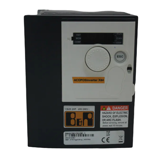
ACOPOSinverter P64new
Migration manual
Version: 1.20 (December 2019)
Order no.: MAACPIX64-ENG
Translation of the original documentation
All values in this manual are current as of its creation. We reserve the right to change the contents of this manual
without notice. B&R Industrial Automation GmbH is not liable for technical or editorial errors and defects in this
manual. In addition, B&R Industrial Automation GmbH assumes no liability for damages that are directly or indirectly
attributable to the delivery, performance or use of this material. We point out that the software and hardware
designations and brand names of the respective companies used in this document are subject to general trademark,
brand or patent protection.
Advertisement
Table of Contents

Related Manuals for B&R ACOPOSinverter X64

Summary of Contents for B&R ACOPOSinverter X64
- Page 1 ACOPOSinverter X64 ACOPOSinverter P64new Migration manual Version: 1.20 (December 2019) Order no.: MAACPIX64-ENG Translation of the original documentation All values in this manual are current as of its creation. We reserve the right to change the contents of this manual without notice.
- Page 3 Safety information 1 Safety information Read through these instructions carefully and familiarize yourself with the device before installing, operating or servicing it. The warning messages listed below are included in all documentation and on the device itself in order to highlight potential risks and hazards, or to indicate specific information intended to explain or simplify a particular procedure.
- Page 4 Safety information be implemented. Since the product is used as a component of an overall system, personal safety must be ensured by selecting an appropriate complete system variant (such as an appropriate machine design, for example). Use of this product in any way other than its expressly permitted use is strictly prohibited and can be potentially dangerous. Only qualified personnel are permitted to install, operate, control and service electrical devices.
- Page 5 Safety information Warning! UNINTENDED OPERATION OF THE EQUIPMENT • When wiring the device, all EMC requirements must be strictly observed. • It is not permitted to operate the product using unspecified or unsuitable settings or data. • Perform a comprehensive commissioning test. Failure to follow these instructions can result in serious injury or death as well as damage to the equipment.
- Page 6 Safety information Danger! EXPLOSION HAZARD Install and use this device only outside of danger zones. Failure to follow these instructions will result in death or serious injury. Machines, controllers and associated devices are usually integrated into the network. Unauthorized persons and malware can gain access to the machine or other devices on the machine's network/fieldbus and connected net- works via insufficiently secured access to software and networks.
- Page 7 This document lists the differences between the two frequency inverter series that must be taken into account during product migration. Advice: ACOPOSinverter P66 is the successor product of ACOPOSinverter X64 and must be used for new systems or for new projects in Automation Studio. ACOPOSinverter X64...
- Page 8 8I64T401100.00X-1 8I64T401100.0X-000 8I64T401500.00X-1 8I64T401500.0X-000 Advice: The ACOPOSinverter P64new is a largely compatible solution for existing B&R customers and not a further development of the ACOPOSinverter X64. Additional functions of the new drive (e.g. safety applications) are not enabled. V 1.20...
- Page 9 3.1 Dimensions and drill hole patterns The following deviations with regard to mechanical data must be observed: Material number Variant ACOPOSinverter P66 / ACOPOSinverter P64new ACOPOSinverter X64 ACOPOSinverter P66 Weight Width Height Depth Height including...
- Page 10 Installation Material number Variant ACOPOSinverter P66 / ACOPOSinverter X64 ACOPOSinverter P66 ACOPOSinverter P64new Drill hole pat- Drill hole pat- Drill hole pat- Drill hole pat- tern width [mm] tern height [mm] tern width [mm] tern height [mm] 8I66S200018.00-000 1-phase - 200 to 240 V - 0.18 kW 121.5...
- Page 11 Preprocessing incoming signals (e.g. edge counting or AB-counter) is no longer possible, for example. If this function is implemented on the ACOPOSinverter X64, an additional X20 module must be implemented during the upgrade, if necessary.
- Page 12 Installation Terminal Description I/O type Electrical characteristics 10 V Power supply for setpoint potentiometer Output Internal power supply for analog inputs • 10 VDC • Tolerance: 0 to 10% • Current: Max. 10 mA Analog voltage input Input Analog input 0 + 10 VDC •...
- Page 13 Installation Terminal Description I/O type Electrical characteristics • 24 VDC power supply (max. 30 VDC) • State 0 if <5 VDC, state 1 if >11 VDC (in source mode) • State 0 if >16 VDC, state 1 if <10 VDC (in sink mode) •...
- Page 14 Installation 3.2.2 ACOPOSinverter X64 Terminal Function Electrical characteristics • NO contact of programmable relay r2 Minimum switching capacity: 10 mA at 5 V (DC power) • Max. switching capacity at resistive load (cos ϕ = 1 and L/R = 0 ms): 2 A at 250 V (AC power) and 30 V (DC power) •...
- Page 15 Installation Terminal Function Electrical characteristics Depending on the I/O configuration, LI3 and LI4 Same characteristics as LI1 and LI2 can be used as: Event counter, gate, frequency and period measurement (LI3 and LI4 cannot be used for library • Logic inputs ACP10SDC.
- Page 16 X2X Link bus. It was equipped with a special compatibility layer to convert controller access to the ACOPOSinverter X64 and prepare it for the ACOPOSinverter P64new. One input and one output have each been implemented for X2X Link. A shield connection and shield grounding are provided.
- Page 17 Interfaces Model number 8I0IF109.400-2 Ambient conditions Temperature Operation -10 to 60°C Storage -40 to 85°C Transport -40 to 85°C Relative humidity Operation 5 to 95%, non-condensing Storage 5 to 95%, non-condensing Transport 5 to 95%, non-condensing Mechanical properties Note Terminal blocks must be ordered separately. 2x 8TB2104.2010-00 (corresponds to 0TB704.9) or 2x 8TB2104.2210-00 (corresponds to 0TB704.91) or 1x 8TB2108.2010-00 or...
- Page 18 The step responses of the internally measured current, the internally calculated speed and the directly measured change in position (measured with an ABR encoder) were randomly recorded for the ACOPOSinverter X64 and compared with those of the ACOPOSinverter P64new. ...
- Page 19 The first diagram shows that the ACOPOSinverter P64new responds in a more agile manner. The increase of the current value is considerably steeper than with the ACOPOSinverter X64. In contrast to the ACOPOSinverter X64, a brief overshoot occurs before the same end value is reached. The second diagram shows that the increased agility has a positive effect on speed control.
- Page 20 Implementation Measurement series 2 An unusual (poorly optimized) configuration was chosen for measurement series two. Despite the increased deviations in the current measurement, only very small deviations from the other process variables occurred. The observations from measurement series 1 could be confirmed. V 1.20...
- Page 21 Implementation V 1.20...
- Page 22 The first diagram shows that the ACOPOSinverter P64new behaves in a similarly agile manner. The increase of the current value is about as steep as with the ACOPOSinverter X64. Just like with the ACOPOSinverter X64, there is a brief overshoot before the approximately same end value is reached. The second diagram shows that speed control is almost running simultaneously.
- Page 23 Implementation Measurement series 2 An unusual (poorly optimized) configuration was chosen for measurement series two. Despite the changed configuration, no major deviations could be generated in the current measurement. For this reason, only very small deviations with regard to the other process variables occur. The observations from measurement series 1 could be confirmed.
- Page 24 Implementation V 1.20...
- Page 25 The first diagram shows that the ACOPOSinverter P64new replacement product responds in a similarly agile man- ner. The increase of the current value is almost as steep as with the ACOPOSinverter X64. In contrast to the ACOPOSinverter X64 original product, there is a higher short-term overshoot before the same end value is reached.
- Page 26 Implementation Measurement series 2 An unusual (poorly optimized) configuration was chosen for measurement series two. By modifying the configuration of the controller, the deviations already mentioned could be increased. However, there is still no noticeable deviation on the axis shown during position detection via the encoder. The observations from measurement series 1 could be confirmed.
- Page 27 Implementation V 1.20...
- Page 28 The first diagram shows that the ACOPOSinverter P64new responds in a more agile manner. The increase of the current value is considerably steeper than with the ACOPOSinverter X64. In contrast to the ACOPOSinverter X64, there is a higher short-term overshoot before it reaches approximately the same end value.
- Page 29 Implementation Measurement series 2 An unusual (poorly optimized) configuration was chosen for measurement series two. By modifying the configuration of the controller, some instability could possibly be generated in the control behavior for the current. Despite this considerable deviation, there was no obvious effect on the stability with regard to the internally calculated value for speed and position monitoring using the encoder.
- Page 30 Implementation V 1.20...
- Page 31 Inhibition](rIn) was defined as Inhibition](rIn). The effect of impermissible. The ACOPOSinverter P64new provides configuration parameter this setpoint check differs considerably from that of the ACOPOSinverter X64, however. For this reason, parameter Inhibition](rIn) is not accessible on the ACOPOSinverter P64new. Warning! The behavior of the ACOPOSinverter P64new is different with regard to limiting the direction of rotation.
- Page 32 With the ACOPOSinverter P64new, bit 11 of control word "CMDD" can still be used for the direction reversal function of the motor. Notice! In contrast to the ACOPOSinverter X64, bit 11 of control word "CMDD" can only be used for the direction reversal function to change the direction of rotation of the connected motor if configuration parameter [Rotating...
- Page 33 Application-based differences 6.9 Ramp switchover (control word "CMI") With the ACOPOSinverter P64new, the command for switching the acceleration/deceleration ramp can no longer be executed using bit 4 of control word "CMI". If the ramp switchover is implemented using bit 4 of control word "CMI", the application cannot be migrated.
- Page 34 Possible solution The manual of the original product contains information about this function. Since this function is not integrated in the user interface of the ACOPOSinverter X64, however, it is not offered for the replacement product. 6.17 Extended control word "CMI The extended control word "CMI"...
- Page 35 Application-based differences Possible solution Control word "CMI" is a device-specific extension that is not required in communication profile DS402. In principle, the device can be used without any limitations even without this additional command word. 6.18 Extended status word "ETI" Extended status word "ETI"...
- Page 36 Problems and solutions 7 Problems and solutions 7.1 Boot loop If the ACOPOSinverter P64new gets stuck in the boot loop after replacement, a 1-to-1 replacement is unfortunately not possible. To continue using the existing Automation Studio project, an updated version of hardware upgrade "8I64xxxxxxx.00X -1"...
Need help?
Do you have a question about the ACOPOSinverter X64 and is the answer not in the manual?
Questions and answers
What's this error InF and the solution
For the B&R inverter X64, the InF error refers to "Internal fault" conditions. Based on the context:
- InF1: Unspecified inverter size (Rating error)
- InF2: Unspecified or incompatible power card
- InF3: Interruption in internal serial communication
- InF4: Internal manufacturing error
- InF6: Unspecified error or incompatible option card
- InF9: Error measuring current
- InFA: Input phase loss error
- InFb: Temperature sensor error (open or short circuit)
- InFE: CPU error (RAM, flash memory, tasks, etc.)
Resolution:
- For InFA (input stage error): Contact B&R Product Support.
- For InFb (temperature sensor error): Replace the temperature sensor or contact B&R Product Support.
- For InFE (CPU error): Switch off and reset the inverter. If the problem persists, contact B&R Product Support.
- For other InF errors like InF1, InF2, InF3, InF4, InF6, and InF9: These indicate internal issues, unspecified errors, or hardware incompatibilities. It is recommended to inspect hardware compatibility, communication links, and contact B&R Product Support for further assistance.
This answer is automatically generated