
Related Manuals for Sensor Electronics SEC 3500 HMI

Summary of Contents for Sensor Electronics SEC 3500 HMI
- Page 1 SEC 3500 HMI Operator Interface Hardware Manual Sensor Electronics Corporation 12730 Creek View Avenue Savage, Minnesota 55378 USA (952) 938-9486 Fax (952) 938-9617 Email sales@sensorelectronic.com SEC P/N: 1460014 Rev / ECO: A / 000209 Page 1 of 26...
- Page 2 Sensor Electronics Corporation including but not limited to, the fitness for a particular purpose. In no event shall Sensor Electronics Corporation be liable for direct, incidental, or consequential loss or damage of any kind connected with the use of its products or failure to function or operate properly.
-
Page 3: Table Of Contents
Table of Contents Contents I. SPECIFICATIONS ........................... 5 II. GENERAL DESCRIPTION ......................6 III. OPERATION ..........................7 IV. INSTALLATION ..........................8 V. DRAWINGS ............................ 9 VI. TESTING ............................. 25 VII. MAINTENANCE ......................... 26 SEC P/N: 1460014 Rev / ECO: A / 000209 Page 3 of 26... - Page 4 Revision History Date Description of Change Page 032113 03/21/13 Initial Release 9/20/2016 Update to Current P/N Scheme Update Specifications Add Installation Steps Add Testing Add Maintenance Add UL2017 Information 10/26/2016 Change model to SEC3500 HMI Add all Components Inside Enclosure to Specs Add Recommended Power Supply Add Earth Ground Callout to Page 9 Add Note about ISO Comm on Repeaters...
-
Page 5: Specifications
I. SPECIFICATIONS Model: SEC3500 HMI Interface RS485 Port: Interactive “Modbus” (expandable to two) RS232 Port: “Statcast” System parameter broadcast Ethernet Port: Remote Screen Access 16 Programmable Relays (expandable to 40) Construction: Powder Coated Steel Dimensions: 16” X 16” X 10” Weight: 45lbs Operating Temperature Rating: 0... -
Page 6: General Description
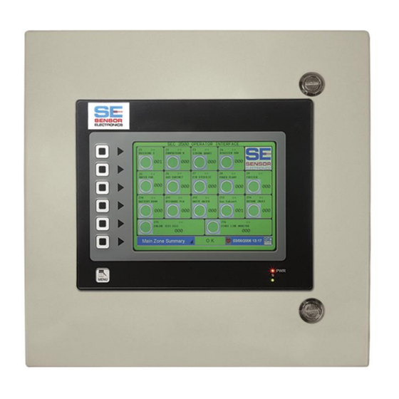
The following conventions are used in this manual. Warning Statement VDC (DC Voltage) SEC 3500 HMI The SEC3500 HMI Operator Interface, an Attendant-Monitored system, continuously interrogates up to 254 system devices over the 9600 baud RS485 Modbus Interface. The OI, operating as the Modbus Master, can communicate with any SEC3XXX Device and any 4-20 transmitter via the SEC3100AIM. -
Page 7: Operation
III. OPERATION The SEC3500 HMI Operator Interface is an intuitive operator interface. For the individual page operations please refer to the following individual instruction manuals on the SEC website: 3500 OI Basic Operators Guide.pdf 3500 OI Startup Basics Guide.pdf StatCast.pdf SEC P/N: 1460014 Rev / ECO: A / 000209 Page 7 of 26... -
Page 8: Installation
The horn needs to be supplied with +24VDC. 6. Sensor Electronics recommends not connecting earth ground and DC common together. Instead connect earth ground to the bolt inside the enclosure. It is located inside the enclosure on the bottom left and is connected to the panel door. - Page 9 SEC P/N: 1460014 Rev / ECO: A / 000209 Page 9 of 26...
-
Page 10: Drawings
V. DRAWINGS Part Number Description 1421901 Mounting and Dimensional Drawing 350000016X16X10 Internal Component Layout 1460015 (separate document) Overall Wiring Diagram Wiring Examples SEC P/N: 1460014 Rev / ECO: A / 000209 Page 10 of 26... - Page 11 SEC P/N: 1460014 Rev / ECO: A / 000209 Page 11 of 26...
- Page 12 SEC P/N: 1460014 Rev / ECO: A / 000209 Page 12 of 26...
- Page 13 WIRING TERMINATION The wiring diagram is for the input power to the SEC 3500 and RS485 Data Highway Connection. Earth Ground Connection (Ground Stud) Enclosure Wall Terminal Description: 2 AMP Circuit Breaker Power for SEC 3500 only DC Common LAN Y DATA A LAN Y DATA B LAN Y ISOLATED DC COMMON LAN X DATA A...
- Page 14 24 VDC 4 5 6 SEC 3500 Terminal Block POWER SUPPLY WIRING EXAMPLE: SEC 3500 TO SEC 3100 TRANSMITTERS AND SEC 3500 – 8 RELAY CONTROLLER SEC P/N: 1460014 Rev / ECO: A / 000209 Page 14 of 26...
- Page 15 (4) BLACK (3) FAULT (N.E.) N.C. (DC COMMON) (2) FAULT (N.E.) COMMON (1) FAULT (N.E.) N.O. BACK VIEW OF SEC 3100 SENSOR ELECTRONICS CORPORATION SEC 3100 WIRING 12730 CREEK VIEW AVE SAVAGE, MINNESOTA 55378 USA (T) 952.938.9486 (F) 952.938.9617 sales@sensorelectronic.com...
- Page 16 TB 1 Relay Wiring TB 2 Relay Wiring High Alarm N.C. 1 Low Alarm N.C. High Alarm Common 2 Low Alarm Common High Alarm N.O. 3 Low Alarm N.O. Fault N.O. 4 Mid Alarm N.C. Fault Common 5 Mid Alarm Common Fault N.C.
- Page 17 SEC 3500-8 RELAY CONTROLLER TB 1 (WIRING CONNECTION FOR POWER AND RS485) TB 2 AND TB 3 (RELAY CONTACT WIRING) SPECIFICATIONS INPUT POWER: 10-30 VDC RELAY CONTACT RATING: 8 AMPS @ 250 VAC OR 8 AMPS @ 30 VDC COMMUNICATION: ISOLATED RS485 (MODBUS) WEIGHT: SEC 3500 –...
- Page 18 TOP VIEW OF SEC 3500 -16 TOP VIEW OF SEC 3500 - 8 RELAY CONTROLLER RELAY CONTROLLER DATA POWER DATA POWER For wiring details refer to Figure A Figure B Figure C Figure A TB 2 (K1-K4) TB 4 (K9-K12) (TB 1) TB 3 (K5-K8) TB 5 (K13-K16)
- Page 19 SEC 3500-8 RELAY CONTROLLER DIMENSIONS SEC 3500 – 16 RELAY CONTROLLER DIMENSIONS SEC P/N: 1460014 Rev / ECO: A / 000209 Page 19 of 26...
- Page 20 The SEC 3100 ISO RS-485 Repeater Module is used in conjunction with the SEC 3100 transmitters and the SEC 3500 HMI Operator Interface or other MODBUS RS-485 data highway systems. The SEC 3100 ISO RS-485 Repeater Module is used to extend the distance of the RS-485 network and increase the number of devices on the RS-485 network.
- Page 21 SEC 3100 AIM Analog Input Module Operation The SEC 3100 AIM is used in conjunction with the SEC 3100 explosion proof transmitter or SEC 3100 DIN transmitter. A non-SEC device with a conventional analog 4 - 20 mA output is wired to the SEC 3100 AIM. The SEC 3100 AIM receives a sourced 4 - 20 mA signal from the device, converts the analog signal into a digital signal compatible with the SEC 3100 transmitter.
- Page 22 SEC 3100 AIM 4-20 mA output + 24 VDC DC Common 4-20 mA Device Pressure Transmitter Open Path Gas Detector Pyrolyzer Temperature Transmitter Fire Detector SEC 3100 Transmitter (back side) SEC 3100 Explosion Proof Transmitter NOTE: Refer to the SEC 3100 Transmitter Instruction Manual for additional wiring connections.
- Page 23 SEC 3100 LIM Logic Input Module Operation The SEC 3100 LIM is used in conjunction with the SEC 3100 explosion proof transmitter or SEC 3100 DIN transmitter. A non-SEC device with normally open contacts is wired to the SEC 3100 LIM. The SEC 3100 LIM receives a Low and High contact closure from the device, converts the input signal into a digital signal compatible with the SEC 3100 transmitter.
- Page 24 SEC 3100 LIM High Alarm Low Alarm + 24 VDC Switch Device Pressure Switch Open Path Gas Detector Air Flow Switch Temperature Switch Fire Detector SEC 3100 Transmitter (back side) SEC 3100 Explosion Proof Transmitter NOTE: Refer to the SEC 3100 Transmitter Instruction Manual for additional wiring connections.
-
Page 25: Testing
VI. TESTING In order to test the system and its functions, Navigate to the 3100 Manual Control page and begin a device Self-Test. This will simulate the sensor going into Low, Mid then High alarm. As the sensor goes through these alarms the 3500 screen should show the sensor going into alarm and respond accordingly (turn fan on/siren/lights/etc.…) depending on the user’s system settings and what the response to those alarms. -
Page 26: Maintenance
VII. MAINTENANCE Maintenance will need to be done by SEC personal. The maintenance needed is minimal. If issues arise and maintenance is needed, please contact Sensor Electronics at 952-938-9486. SEC P/N: 1460014 Rev / ECO: A / 000209 Page 26 of 26...
Need help?
Do you have a question about the SEC 3500 HMI and is the answer not in the manual?
Questions and answers