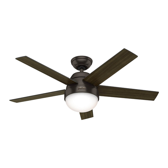
Download Print this page

Advertisement

Quick Links

#50640, 50641
9.2kg ±1kg
Stile
Installation Manual
Manual de instalación
Installationhandbuch
Manuel d'installation
Manuale di installazione
Εγχειρίδιο εγκατάστασης
Kurma klavuzu
Buku petunjuk instalasi
Manual de Instalação
©2019 Hunter Fan Co.
MB543 r032019

Advertisement

loading

Summary of Contents for Hunter Stile

  • Page 1 Stile Installation Manual Manual de instalación Installationhandbuch Manuel d’installation Manuale di installazione Εγχειρίδιο εγκατάστασης Kurma klavuzu Buku petunjuk instalasi Manual de Instalação #50640, 50641 9.2kg ±1kg ©2019 Hunter Fan Co. MB543 r032019...
  • Page 2 This manual will help you install, operate, and maintain your new fan. These instructions are designed to make installation and assembly as simple and efficient as possible. Important Instructions: Keep Instructions for future use English WARNING! Be sure to read the entire manual before beginning installation and save any extra parts for future use. The mounting of the suspension system shall be performed by the manufacturer, its service agent, or suitably qualified persons.
  • Page 3 Αυτό το εγχειρίδιο θα σας βοηθήσει να εγκαταστήσετε, να χειρίζεστε και να συντηρείτε τον καινούριο σας ανεμιστήρα. Οι παρούσες οδηγίες είναι σχεδιασμένες να απλοποιούν και να βελτιστοποιούν κατά το δυνατό την εγκατάσταση και τη συναρμολόγηση. Ελληνικά Σημαντικές οδηγίες: Φυλάξτε τις οδηγίες για μελλοντική χρήση ΠΡΟΕΙΔΟΠΟΙΗΣΗ! Βεβαιωθείτε...
  • Page 4 2,6 m ,76 m 2,3 m STANDARD MOUNTING Standard Mounting is the most common way to mount a ceiling fan. Fan Mounting Options Blades must be more than 2.3m from the floor There are different ways to mount your ceiling fan, depending on your needs and the style of your ceiling.
  • Page 5 < 34º ANGLED MOUNTING Angle Mounting is especially useful for vaulted or angled ceilings. If angle mounting, orient the ceiling plate with the arrows pointing toward the ceiling peak. MONTAJE EN ÁNGULO El montaje en ángulo es especialmente útil para techos abovedados o Si está...
  • Page 6 POWER BUMPERS Turn Power OFF Make sure all four (4) bumpers are still attached. ENERGÍA TOPES La energía DESCONECTE Asegúrese de que los cuatro (4) topes estén aún acoplados. STROM PUFFER Schalten Sie den Strom Stellen Sie sicher, dass alle (4) Dämpfer nach wie vor befestigt sind. ALIMENTATION AMORTISSEURS COUPER l’électricité.
  • Page 7 FOR CONCRETE CEILINGS If you have a concrete ceiling, follow steps 1-4 before proceeding to Identify the supply mains in the ceiling and drill two holes using the page 12. If you have a non-concrete ceiling, follow steps 5-8 before ceiling plate (A) as a guide for measurement and accuracy.
  • Page 8 FOR CONCRETE CEILINGS Drive the M6 x 50 mm expansion anchors (A) into the holes Thread the supply mains (A) through the center hole of the until there is only approximately 10 mm of exposed anchor. ceiling plate (B). PARA UN TECHO DE CONCRETO: Pase expansión ancla M6 x 50 mm (A) a través de los agujeros Pase los alambres de la alimentación de la red (A) a través hasta que los extremos son de 10 mm de anclaje visible.
  • Page 9 FOR CONCRETE CEILINGS Align the Anchor bolts (A) with the oval slots in the ceiling plate (C). Push the Ceiling Plate onto the anchors (B) until the rubber isolators (D) are tight against the ceiling. Place the flat washer, spring washer, and nut (E) onto the anchor bolt and secure tightly. Proceed to page 12. PARA UN TECHO DE CONCRETO: Alinee los pernos de anclaje (A) con las ranuras ovaladas de la placa de techo (C).
  • Page 10 FOR NON-CONCRETE CEILINGS Drill two pilot holes into the wood support structure using the Place a flat washer (A) on both of the wood screws (B). ceiling plate (A) as a guide for measurement and accuracy. PARA TECHOS QUE NO SON DE CONCRETO Taladre dos agujeros piloto en la estructura de soporte de Coloque una arandela plana (A) en ambos tornillos para madera madera usando la placa de techo (A) como una guía para...
  • Page 11 FOR NON-CONCRETE CEILINGS Thread the supply mains (A)through the center hole of the Raise the ceiling plate (A) and align two opposing oval slots with ceiling plate (B). the pilot holes (B). Insert and tighten the two wood screws (C) with washers (D) to secure the ceiling plate (A) to the ceiling.
  • Page 12 WARNING! To reduce the risk of fire, electrical shock, or motor damage, do not lift or carry the fan by the lead wires. To prevent damage to the wires on the bottom of the fan assembly, do not sit fan on hard surface. Use foam inside box as support. The pipe adapter has a special coating on the threads.
  • Page 13 Remove the pre-installed setscrew (A). Retire el tornillo de fijación (A) instalado previamente. Entfernen Sie die vorinstallierte Stellschraube (A). Retirer la vis de blocage pré-installée (A). Rimuovere le viti di fissaggio preinstallate (A). Αφαιρέστε τον προσυναρμολογημένο ακέφαλο κοχλία (A). Önceden takılmış olan ayar vidasını (A) sökün. Lepaskan sekrup pengikat yang telah terpasang (A).
  • Page 14 Slide the downrod sleeve (A) up the downrod. Insert the Slide the downrod ball (A) up the length of the downrod down rod pin (B) into the pin hole (C) on the top of the pipe. Align the downrod pin (B) with the notches in the downrod.
  • Page 15 Hand tighten the downrod (at least 4-5 full turns) until it Insert the downrod ball screw (A) into the hole in the top of the stops. downrod ball. Apriete girando la varilla (por lo menos 4-5 vueltas completas) Inserte el perno del tubo vertical (A) en el orificio del pasador hasta que se detenga.
  • Page 16 Tighten the setscrew with pliers. DO NOT HAND TIGHTEN. Put the wires and downrod through the canopy. Let the canopy sit loosely on top of the fan. If the setscrew is not tightened securely, the fan may fall. Apriete el tornillo de fijación con un alicate. NO APRIETE A Pase los alambres y la varilla a través de la campana.
  • Page 17 DO NOT PICK THE FAN UP BY THE CANOPY OR WIRES. Place the downrod ball into the slot in the ceiling bracket NO LEVANTE EL VENTILADOR AGARRANDO LA CAMPANA O LOS CABLES. Coloque la bola de la varilla en la ranura del soporte de techo.
  • Page 18 DOWNROD INSTRUCTIONS Shorter Downrod (A) for fans installed close to ceiling (Included) If you need a different downrod length follow these steps: Standard Downrod (B) for ceilings 2,4-3 m (8-10’) high (Included) Steps 6-10 to reassemble with new pipe Longer Downrod (C) for angled ceilings or ceilings 3 m (10’) or higher (Sold Separately) INSTRUCCIONES PARA EL TUBO Tubo más corto (A) para ventiladores instalados cerca del techo (incluido)
  • Page 19 WARNING! To avoid possible electric shock, before wiring the fan, disconnect power by turning off the circuit breakers to both the outlet box and its associated wall switch location. If you cannot lock the circuit breakers in the off position, securely fasten a prominent warning device, such as a tag, to the service panel.
  • Page 20 WIRING Pull the supply mains (A) through the side of the hanger bracket This is the procedure for steps 19-23. Thread the end of each (B). wire into the terminal block (A) on the hanger bracket, then secure each supply main (B) by tightening the small setscrews (C).
  • Page 21 WIRING Earth wire (A) (green/yellow) to terminal (B) marked Neutral wire (A) (blue) to terminal (B) marked "N". Earth wire from downrod (C) to terminal (B) marked CABLEADO Alambre de tierra (A) (verde/amarillo) al terminal (B) marcado Alambre neutro (A) (azul) a terminal (B) marcado "N". .
  • Page 22 WIRING Line wire (A) (brown) to terminal (B) marked "L". An additional “L” terminal is provided for separate control of the light kit if a separate line is provided for that purpose. CABLEADO Alambre de línea (A) (marrón) a terminal (B) marcado "L". Se proporciona una “L”...
  • Page 23 WIRING Make wire connections using the 4-pin plugs coming from the Place receiver in ceiling bracket. Excess wire may be placed into the receiver, fan, and hanger bracket as shown. Connect the female plug outlet box for non-concrete ceilings or inside the hanger bracket for concrete ceilings.
  • Page 24 CANOPY WARNING! Be sure no bare wire or wire strands are visible after Position the canopy so that, when lifted into place, the making connections. Failure to complete the following canopy fits into the hanging bracket as shown. steps carefully could result in the fan falling. ¡...
  • Page 25 Lift the canopy into place so that the screw holes(A) are Insert the two canopy screws found in the hardware bag. aligned. Inserte los dos tornillos de la campana que se encuentran en Levante la campana para ponerla en posición de manera que los agujeros para tornillos (A) estén alineados.
  • Page 26 Attach each blade to a blade iron using blade washers, Partially install two light kit assembly screws, found in the found in the hardware bag, and blade assembly screws, hardware bag, halfway into the motor housing as shown. found in the hardware bag.
  • Page 27 Feed the 9-pin plug connector coming from the bottom of the motor housing through the center hole in the light kit Align the keyhole slots in the top of the light kit assembly assembly. Connect it to the plug connector found in the with the partially installed assembly screws.
  • Page 28 Carefully push all switch housing components into the Insert a third light kit assembly screw, found in the switch housing, then install the switch housing plate using hardware bag, into place and tighten all three screws two light kit assembly screws, found in the hardware bag.
  • Page 29 Lift the globe and align the notches (A) in the globe with the tabs Install a light bulb in each socket. (B) in the light kit. Attach the glass bowl to the light kit by twisting it clockwise until it snaps into place. Instale una bombilla en cada uno de los portalámparas.
  • Page 30 To access the battery compartment, remove the battery door from the transmitter assembly. The battery should be Turn Power ON installed with the positive (+) side up. Replace with a CR2032 battery when necessary. Para acceder el compartimento de la batería, retire la Encienda el compuerta de la batería del conjunto del transmisor.
  • Page 31 The remote transmitter is already paired to the receiver and ready to use. Note: If your need to pair your remote, remove the battery door. Cycle power to the The remote transmitter is already paired to the receiver and fan by turning power off and back on at the wall switch (or circuit breaker if necessary). ready to use.
  • Page 32 Option 1: Using Screws Choose your cradle installation location. Slide the cradle onto the mounted bracket. If you are installing into drywall, drill two 9/64 width holes using the cradle bracket as a guide. Gently hammer the included drywall anchors into the pre-drilled holes. Install the cradle bracket to the wall with the included screws.
  • Page 33 Option 2: Using Adhesive Strip Slide the cradle onto the mounted bracket. Apply the adhesive sticker to the back of cradle bracket per the instructions on the adhesive sticker. Press the cradle bracket against the wall and hold firmly for 30 seconds.
  • Page 34 Fan Operation: Slide the remote into the cradle when not in use. Press and quickly release the fan button on the remote control to turn the fan OFF or ON. Use the fan control directional pad to raise or lower the fan to the desired speed. Light Operation (for fans with a light kit): Press and quickly release the light button on the remote control to turn the light OFF or ON.
  • Page 35 WARNING! To reduce the risk of burns and eye damage or electrical shock, disconnect power and allow bulb to cool for at least 5 minutes before replacing. Do not touch the bulb. Do not look directly at lighted lamp. Replace the glass shade, if broken. ¡ADVERTENCIA! Para reducir el riesgo de quemaduras y daños a los ojos o choque eléctrico, desconecte la alimentación eléctrica y permita que la bombilla se enfríe por lo menos 5 minutos antes de reemplazarla.
  • Page 36 Changing the bulbs - rotate the globe counter clockwise and To switch the direction of air flow, move the reverse switch to lower once released from the tabs. Replace bulbs with bulbs of the opposite position. You will need to remove the light kit the same type and wattage.
  • Page 37 In warm weather, ceiling fans work best by blowing air In cool weather, set your fan to draw air upward (clockwise) downward (counterclockwise) providing the room with a to distribute the warmer air trapped at the ceiling without cool breeze. causing a draft.
  • Page 38: Καθαρισμός Και Συντήρηση

    Painted and high-gloss blades may be cleaned in the same manner Pulizia e Manutenzione as the fan finish. If you need parts or service assistance contact your Hunter Καθαρισμός και συντήρηση Fan retailer or visit out website at: http://www.HunterFanInternational.com.
  • Page 39: Nettoyage Et Entretien

    Si vous avez besoin de pièces ou d’aide, communiquez Per pezzi di ricambio o assistenza contattare il rivenditore avec votre revendeur Hunter Fan ou rendez-nous visite Hunter Fan o visitate il nostro sito Web all’indirizzo: sur notre site Web au: http://www.HunterFanInternational. http://www.HunterFanInternational.com.
  • Page 40: Troubleshooting

    Se precisa do serviço de assistência ou peças, contacte o seperti lapisan finishing kipas. distribuidor Hunter Fan ou vá ao nosso website em: http://www.HunterFanInternational.com. Jika Anda membutuhkan komponen atau bantuan layanan, hubungi penjual ritel Kipas Hunter Anda atau kunjungi situs web kami di: http://www.HunterFanInternational.com.
  • Page 41: Risoluzione Problemi

    Deutsch Español Störungsbeseitigung Localización de fallas Problem: Nichts passiert, der Ventilator bewegt sich nicht. Problema: No sucede nada; el ventilador no se mueve. Lösung: Solución: • Schalten Sie die Stromzufuhr ein, ersetzen Sie die • Encienda la alimentación eléctrica, reemplace el fusible o Sicherung oder stellen Sie den Unterbrecher zurück.
  • Page 42 Ελληνικά Türkçe Αντιμετώπιση προβλημάτων Sorun Giderme Πρόβλημα: Δεν συμβαίνει τίποτα. Ο ανεμιστήρας δεν κινείται. Problem: Hiçbirşey olmuyor; fan hareket etmiyor. Λύση: Çözüm: • Ενεργοποιήστε τον ανεμιστήρα, αντικαταστήστε την • Gücü açın, sigortayı değiştirin, ya da şalteri sıfırlayın. ασφάλεια ή επαναφέρετε τον αυτόματο διακόπτη σε θέση •...

This manual is also suitable for:

5064050641