Hunter Swanson Installation Manual
Hide thumbs
Also See for Swanson:
- Installation manual (4 pages) ,
- Installation manual (4 pages) ,
- Installation manual (4 pages)

Related Manuals for Hunter Swanson


Summary of Contents for Hunter Swanson
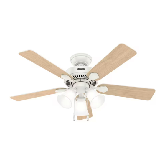
- Page 1 Swanson Installation Manual Model: 52777 Fresh White 52789 Matte Black 52779 Matte Silver 52781 Noble Bronze Fan weight ±2 lbs: 14.6 lbs (6.6 kg) ©2023 Hunter Fan Co. PG4172 r110823...
- Page 2 - All wiring must be in accordance with national and local electrical codes ANSI/NFPA 70. If you are unfamiliar with wiring, use a qualified electrician. c.2 - Use only Hunter replacement parts. This equipment has been tested and found to comply with the limits for a Class B digital device, pursuant to part 15 of the FCC Rules. These limits are designed to provide reasonable protection against harmful interference in a residential installation.
- Page 3 We recommend that you pull everything out of the box and lay it out. We have grouped the drawn components below with the hardware you’ll need for those Hunter Pro Tip: parts. The screws below are drawn to scale to make it easier to identify what piece of hardware is needed to install each component.
-
Page 4: Choosing The Right Installation Location
A little more information on Angled Mounting: For optimum performance and appearance, a longer downrod should be used with your Hunter ceiling fan when installing on high or angled ceiling. If your ceiling is angled greater than 34° you will also need an Angled Mounting Kit. - Page 5 You have two options for installation. Pick which one works best for your location. Remove any existing Hunter Pro Tip: bracket prior to installation. Only use the provided Hunter ceiling bracket that came in your fan’s box. The machine screws are the ones that came with your outlet box.
-
Page 6: Hanging The Fan
1886 Installing the Downrod Follow below if you are using the downrod that came pre-assembled in your box. Need to install a longer or shorter downrod? Check out the guide at the end of this manual. DO NOT NOTICE REMOVE SETSCREW COMPLETELY To prevent damage to fan,... -
Page 7: Installing The Canopy
1886 Making Connections for the Receiver and the Fan From receiver From receiver From fan From fan Connect wiring harness from ceiling Connect both wiring harnesses from fan to Connect the grounding wire plug from the bracket to the wiring harness from the the wiring harness from the receiver. -
Page 8: Installing The Blades
1886 Installing the Blades: Put the blade washers, found in the hardware bag, onto the blade screws, found in the hardware bag. Then install the blade screws to secure each blade to a blade iron. Repeat x5 Blade Screw Washer Note: Fan style may vary. - Page 9 1886 Assembling the Light 2 of 3 1 of 3 Upper Switch Upper Switch Housing Screw Housing Screw Insert a third screw, found in the Feed the wire plug through the center hardware bag, into place and hole of the upper switch housing, then tighten all three screws.
- Page 10 1886 Installing the Pull Chains Attach the pull chain pendants to the light and fan pull chains. To start the fan, pull the chain with the fan icon and you will hear a single beep for confirmation. Repeat the process until you reach your desired speed.
-
Page 11: Troubleshooting
1-888-830-1326 use of improper parts or accessories, failure to provide maintenance to the fan, or acts of Please do not ship your fan or any fan parts to Hunter. Delivery will be refused. God (e.g. flood). ORIGINAL PURCHASER’S SOLE AND EXCLUSIVE REMEDY FOR A CLAIM OF ANY KIND What Does This Warranty Cover? WITH RESPECT TO THIS PRODUCT SHALL BE THE REMEDIES SET FORTH HEREIN. - Page 12 1886 Downrod If you need a different downrod length follow these steps: Remove ball screw (A). Slide ball down (A), remove small metal pin (B) and ground screw (C). Remove ball (A), inner sleeve (B) and downrod (C) from fan body and wiring harnesses.
Need help?
Do you have a question about the Swanson and is the answer not in the manual?
Questions and answers