Table of Contents
Advertisement
Quick Links
Advertisement
Table of Contents

Subscribe to Our Youtube Channel
Related Manuals for Extreme Networks ExtremeCloud Appliance E3120

Summary of Contents for Extreme Networks ExtremeCloud Appliance E3120
- Page 1 ™ ExtremeCloud Appliance E3120 Installation Guide 9036028-00 Published June 2019...
- Page 2 Copyright © 2019 Extreme Networks, Inc. All rights reserved. Legal Notice Extreme Networks, Inc. reserves the right to make changes in specifications and other information contained in this document and its website without prior notice. The reader should in all cases consult representatives of Extreme Networks to determine whether any such changes have been made.
-
Page 3: Table Of Contents
Table of Contents Preface............................4 Conventions..................................... 4 Providing Feedback to Us..............................5 Getting Help.....................................5 Documentation and Training............................6 Chapter 1: Overview........................7 E3120 Control Panels................................7 Hard Drive LED Indicator Patterns..........................9 Chapter 2: Hardware Installation.................... 11 Verifying the Box Contents..............................11 Attaching the Front Bezel............................... 12 Power Supply Options.............................. -
Page 4: Preface
Preface This section discusses the conventions used in this guide, ways to provide feedback, additional help, and ® other Extreme Networks publications. Conventions This section discusses the conventions used in this guide. Text Conventions The following tables list text conventions that are used throughout this guide. -
Page 5: Providing Feedback To Us
Preface Providing Feedback to Us Quality is our first concern at Extreme Networks, and we have made every effort to ensure the accuracy and completeness of this document. We are always striving to improve our documentation and help you work better, so we want to hear from you! We welcome all feedback but especially want to know about: •... -
Page 6: Documentation And Training
Hardware/Software Compatibility Matrices https://www.extremenetworks.com/support/compatibility-matrices/ White papers, data sheets, case studies, https://www.extremenetworks.com/resources/ and other product resources Training Extreme Networks offers product training courses, both online and in person, as well as specialized certifications. For more information, visit www.extremenetworks.com/education/. ExtremeCloud™ Appliance E3120... -
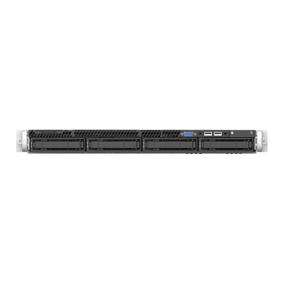
Page 7: Chapter 1: Overview
Overview E3120 Control Panels Hard Drive LED Indicator Patterns E3120 appliance is a high-end ExtremeCloud Appliance that supports five thousand standalone devices, fifty thousand users, and provides availability for up to ten thousand devices and hundred thousand users, with any client distribution between appliances. Attention Only qualified personnel should perform installation procedures. - Page 8 Overview E3120 back panel layout Label Description Power supply module #1 Retention strap receiver hole Power supply module #2 bay for redundant power supply Port 1 (Data Port 1) 1/10GbE, RJ45 Port 2 (Data Port 2) 1/10GbE, RJ45 Port 3 (Data Port 3) 1/10/25/40GbE, QSFP28 Port 4 (Data Port 4) 1/10/25/40GbE, QSFP28 Video connector RJ45 Serial-A Port...
-
Page 9: Hard Drive Led Indicator Patterns
Overview Label Description System ID button with integrated LED NMI button Data Port 1 activity LED Data Port 2 activity LED Not used Not used System cold reset button Drive activity LED System status LED Power button with integrated LED Hard Drive LED Indicator Patterns The hard drive has one LED indicator visible from the front of the system —... - Page 10 Overview Table 3: System LED patterns LED Pattern System Status Description Solid green Indicates that the system is normally running without any errors. 1 Hz blinking green Issues with the system Indicates that: • There might be redundancy loss in the power supply or fan. •...
-
Page 11: Chapter 2: Hardware Installation
Hardware Installation Verifying the Box Contents Attaching the Front Bezel Power Supply Options Connecting to a Power Source To prepare for Hardware Installation of E3120: Match the model number on the purchase order with the model number in the packing list and on the E3120 appliance. -
Page 12: Attaching The Front Bezel
The power cord needs to be purchased separately for the respective deployment country. It can be ordered at https://www.extremenetworks.com/powercords. 2 Perform a visual inspection of the appliance for any physical damage. Contact Extreme Networks Support Portal if there is any damage. - Page 13 Hardware Installation Each power supply has a single bi-color LED to indicate power supply status. The LED indicator patterns are described in the following table. Table 6: Power supply status LED indicator patterns Power supply condition LED pattern Output On and OK Green No AC power to all power supplies AC present/ Only 12VSB On (PS Off) or PS in cold...
- Page 14 Hardware Installation 3 Push the power supply module into the bay until it locks into place. Figure 2: Installing a power supply module Connect the unit to a power source. Removing a Power Supply To remove a power supply module: Detach the power supply cord from the power supply module that needs to be removed.
- Page 15 Hardware Installation 2 Pull the power supply module using the handle, while pushing the latching tab outward to disengage the power supply module from the unit. Figure 3: Removing a power supply module Label Description Handle Latching tab Replacing a Power Supply To replace a power supply: Detach the power supply cord from the power supply module that needs to be removed: Release the slider strap on the power supply cord by pushing down the slider tab.
-
Page 16: Connecting To A Power Source
Hardware Installation 2 Pull out the power supply module using the handle, while pushing the green latch on the power supply module outward to remove the power supply module. Note The appliance requires one power supply to operate the system normally. Remove and replace only one power supply module at a time in a system that is powered on. - Page 17 Hardware Installation Attach the power cord to the power supply module: Insert the locking tab end of the retention strap into the receiver hole of the power supply unit, located to the right of Power Supply #1. 2 Adjust the slider of the retention strap by pushing up the locking tab on the bottom of the slider. 3 If you are using another power cord to create an optional redundant power supply, connect the two AC power cords to power supplies #1 and #2.
-
Page 18: Chapter 3: Initial Network Connection And Configuration
Initial Network Connection and Configuration Configuring the Management Interface via Console Port Configuring the Management Interface via the Management Port Connecting the Data Ports Configuring the Management Interface via Console Port The E3120 must be upgraded to the latest ExtremeCloud Appliance firmware before installing the appliance on the network. -
Page 19: Configuring The Management Interface Via The Management Port
6 Disconnect your laptop from the management port of the appliance. 7 Connect the appliance’s management port to the enterprise Ethernet LAN. 8 Log on to Extreme Networks. Note The system is now visible to the enterprise network. Refer to the ExtremeCloud Appliance... - Page 20 3 Verify that the RJ45 connectors on the twisted pair segment have the proper pinouts, and check the cable for continuity. 4 If a link is not established, contact Extreme Networks Support. Data ports 3 and 4 provide QSFP28 ports that can support 40Gbps transceivers, as well as 1, 10, and 25 Gbps transceivers through special adapters.
- Page 21 Initial Network Connection and Configuration Port LED Patterns RJ45 Port LEDs (Management Port) LED Type LED Pattern Status Indication Network Speed (Left) 10 Mbps Green 100 Mbps Amber 1000 Mbps (1 Gbps) Link Activity (Right) No link Solid Green Active link Blinking Green Data traffic activity Port LEDs (Data Ports 1 and 2)
-
Page 22: Chapter 4: Specifications
Specifications Physical Specifications • Dimensions Length: 31.25" • Width: 17.25" • Height: 1.7" Environmental Specifications Operating Temperature +5°C to +40°C (+32°F to +104°F) Relative Humidity 0% to 95% (non-condensing) ExtremeCloud™ Appliance E3120... -
Page 23: Chapter 5: Regulatory Information
Regulatory Information Regulatory Compliance Information Federal Communications Commission (FCC) Notice Industry Canada, Class A CE Notice Japan (VCCI) - Voluntary Control Council for Interference Class A ITE BSMI EMC Statement - Taiwan Supplement to Product Instructions Hazardous Substances European Waste Electrical and Electronic Equipment (WEEE) Notice Regulatory Compliance Information For complete regulatory compliance and safety information, refer to the document Intel®... -
Page 24: Ce Notice
Regulatory Information Cet appareil numérique respecte les limites bruits radioélectriques applicables aux appareils numériques de Classe A prescrites dans la norme sur le matériel brouilleur: “Appareils Numériques”, NMB-003 édictée par le Ministre Canadian des Communications. CE Notice This product has been determined to be in compliance with 2006/95/EC (Low Voltage Directive), 2004/108/EC (EMC Directive). -
Page 25: Supplement To Product Instructions
Regulatory Information Supplement to Product Instructions Hazardous Substances This product complies with the requirements of Directive 2011/65/EU of the European Parliament and of the Council of 8 June 2011 on the restriction of the use of certain hazardous substances in electrical and electronic equipment. -
Page 26: European Waste Electrical And Electronic Equipment (Weee) Notice
Regulatory Information European Waste Electrical and Electronic Equipment (WEEE) Notice In accordance with Directive 2012/19/EU of the European Parliament on waste electrical and electronic equipment (WEEE): The symbol above indicates that separate collection of electrical and electronic equipment is required. 2 When this product has reached the end of its serviceable life, it cannot be disposed of as unsorted municipal waste. -
Page 27: Index
Index Box Contents 11 Open Source Declaration 6 conventions Redundant Power Supply, Power Supply Module, Installing notice icons 4 a Power Supply, Redundant Power Supply Installation 13 text 4 Regulatory Information, Compliance Information, Regulatory & Compliance 23 Regulatory Information, Hazardous Substances 25 Regulatory Statement, BSMI Statement, EMC Statement, Data Ports, Connecting the Data Ports 19 BSMI EMC Statement 24 documentation...
Need help?
Do you have a question about the ExtremeCloud Appliance E3120 and is the answer not in the manual?
Questions and answers