Table of Contents
Advertisement
Quick Links
Advertisement
Table of Contents

Related Manuals for Alton Evolution


Summary of Contents for Alton Evolution
- Page 1 05/13...
-
Page 2: Table Of Contents
Optional Cedar Panels 25-29 Packing List 30-31 Thank you for purchasing your new Alton cold frame. We recommend you familiarise yourself with the instructions and read all safety information before you commence assembly. This instruction manual is also available online at www.greenhousepeople.co.uk in the technical help section should you need to reprint it. -
Page 3: Front Assembly
Front Assembly To start building your cold frame you need the two components below. First use the drill bit provided to drill a pilot hole through the bottom of the mortise. It Pilot hole is important to always drill pilot holes before inserting a screw to prevent the parts from splitting. - Page 4 Front Assembly External Dia. 3 Pilot hole EV0805 Top View Diagram 2 Now take the front top rail and drill a pilot hole through the back of the mortise slot as you did before with the cill, diagram 2. Slot this onto the top of the middle glazing bar and fix with an 80mm screw, diagram 3.
- Page 5 Front Assembly You now need to fit the front corner bars, before doing this drill pilot hols in the bottom of the bar shown in diagram 4. This is showing the left hand bar, you will need to measure from the opposite faces for the right hand bar.
-
Page 6: Rear Assembly
Rear Assembly As before drill a pilot hole through the mortise then slot the rear middle bar into the rear cill. Fix with a 50mm screw. Dia. 6 Pilot hole External EV0800 Diagram 6 Top View... - Page 7 Rear Assembly Now drill pilot holes in the rear top rail, diagram 7. This time you need to drill 3 holes, one in Pilot hole each mortise, as shown below. You can then slot the top rail onto the top of the middle bar.
- Page 8 Rear Assembly Again before you fit the rear corner bars drill pilot holes as shown in diagram 9. Slot these onto the rear top rail and fix to the rear cill with an 80mm screw, diagram 10. Dia. 10 Diagram 9 Diagram 10...
- Page 9 Rear Assembly Now fix the top of the rear corners to the top rail with 80mm screws as shown below. Internal...
-
Page 10: Frame Assembly
Frame Assembly Now you have the front and rear frame assembled you can fit the side cills. First of all take the front frame and one side cill, slot this into the mortise hole and fix with an 80mm screw (diagram 11). Repeat this at the other end of the front frame. - Page 11 Frame Assembly Next you need to fit the top side rails. You should slot this into place and drill pilot holes in situ. Diagram 12 and 13 show the position of the hole along the bar, make sure you drill down vertically so you screw into the correct section of timber below. The holes should be in the centre of the top side rail.
- Page 12 Frame Assembly Now the pilot holes are drilled you can fix the top side rail with a 50mm screw at the top (diagram 14) and an 80mm screw at the bottom (diagram 15). Repeat this on the right hand rail. Dia.
-
Page 13: Base Assembly
Base Assembly Now the frame is complete you can move that to one side and assemble the base sections. Lay them out as shown below. Use the 4 corner brackets (EV0311M) with the M6 nuts and bolts supplied to join the sections together. For now just fit the nuts finger tight. Dia. - Page 14 Base Assembly External Now lower the frame onto the base, you may find you need to adjust some of the corner brackets to allow the frame to slot onto the base. Once fitting well tighten the nuts. Use 25mm screws to fix the aluminium base to the frame.
-
Page 15: Glazing
Next insert the side pane and fix in place with the capping sections that only have one channel. Fix with 25mm screws. You can then fix the side cloaking board (EV0826) as described below. (Aluminium part numbers shown in brackets) Alton Evolution Cold Frame 2ft x 4ft Glass List Description: ... - Page 16 Glazing Now fit the side capping, push this tight up against the side cloaking board and fix with 25mm screws. EV0847 (EV0867M) Continue working round the cold frame by glazing the front. Insert the front pane and fix with the first piece of capping, the capping should be flush with the top of the glazing bar it is being fixed to.
- Page 17 Glazing Insert the next pane and fix with the remaining 2 front capping pieces. The middle capping will need a 40mm screw in the bottom hole. EV0844 (EV0864M) EV0844 (EV0864M) 50mm Next attach the horizontal capping with 25mm screws. This should sit flush on top of the capping and glazing bars.
- Page 18 Glazing If you haven’t already done so glaze the right hand end section as you did before. Glaze the rear of the cold frame with the same method as you did with the front. Remember the bottom hole on the middle capping will need a 40mm screw.
-
Page 19: Lid Assembly
Lid Assembly NB Can be supplied in 2 parts Dia. 18 Diagram 18 You can now start fitting the lid to the cold frame. Take the top hinge board (EV0832) and the top hinge (EV0835M), position these along the top edge of the cold frame and fix with 40mm screws. - Page 20 Lid Assembly You can now fit the lid supports to the frame. Use a 50mm screw and 2 x M6 washers. Screw through the pre-drilled hole in the support into to the inside face of the front top rail. Refer to diagram 19 below for the position.
- Page 21 Lid Assembly Repeat this for the second support, again checking the tightness of the screw allows the prop to move without too much effort.
- Page 22 Lid Assembly Dia. 20 Dia. 21 Take the vent frame that is ready assembled and fix the vent hinge to one Diagram 20 end through the 4 pre drilled holes using the 19mm screws, diagram 20. Make a pilot hole before fixing the 19mm screw in the back of the vent to prevent it splitting.
- Page 23 Lid Assembly Next fit the handle to the lid, use 25mm screws to attach this tight under the lip of glass at the bottom of the vent. (This acts as a handle but will also protect the front edge of the glass). Dia.
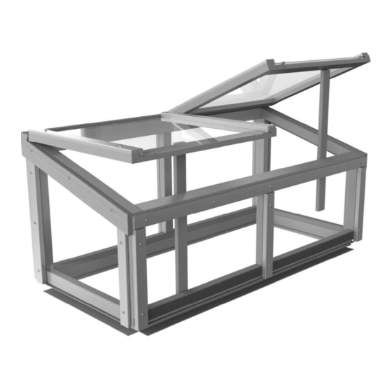
- Page 24 Lid Assembly Your glazed cold frame is now complete! N.B. When moving your cold frame you should pick it up by the recess in the base, just below the glass. Remember it is easy to remove the lid so this is also a good idea when lifting the cold frame.
-
Page 25: Optional Cedar Panels
Cedar Panel Installation (Optional) This is a fully flexible panel kit, if you want to part glaze the cold frame and only use some of the boards this is entirely possible. So it is worth considering this before you start. All panel capping is fitted using 40mm screws Insert the side panel and fix the... - Page 26 Cedar Panel Installation (Optional) Insert the front panel and fix with the first piece of front panel capping, the capping should be flush with the top of the glazing bar it is being fixed to. You should keep the gap between the front capping and the side capping as small as possible.
- Page 27 Cedar Panel Installation (Optional) Next attach the horizontal capping, this should sit flush on top of the front panel capping. If you haven’t already done so fit the right hand end section as you did before. With the left 50mm...
- Page 28 Cedar Panel Installation (Optional) Install the rear panels with the same method as you did with the front. Once the vertical capping is fitted you can then install the horizontal capping as shown opposite.
- Page 29 Cedar Panel Installation (Optional) Once you have finished installing the panels return to page 19 for the fitting of the lid. 50mm...
-
Page 30: Packing List
Cold Frame Top Hinge 4ft EV0835M 1348mm **MOSS** 1 EV0838M Cold Frame Front and Rear Base 4ft EV0838M 1216mm **MOSS** 2 EV0841M Cold Frame Side Base 2ft EV0841M 513mm **MOSS** 2 D119 Silicone Clear 80ml 1 INS Alton Evolution Cold Frame Instruction Manual 1 Alton Evolution Cold Frame 2ft x 4ft Cedar Panels Description: Product Code Description Quantity EV0885 Cold Frame Front Panel EV0885 610x347mm 2 EV0886 Cold Frame Rear Panel EV0886 610x501mm 2 ... - Page 31 Packing List Smalls Pack for Alton Evolution Cold Frame 2ft x 4ft Description: Product Code Description Quantity D174M Base bracket D174 ***MOSS*** 4 EV0311M ALU Base Joining Bracket EV0311 60mm **MOSS** 4 EV0313M Glass Stop EV0313 **MOSS** 4 EV0328 19mm x 4 Pan Pozi A2 Stainless screw 12 EV0331 25mm x 4 Pan Pozi woodscrew A2 SS EV0331 61 EV0332 40mm x 4 Pan Poz A2 SS woodscrew EV0332 11 ...
- Page 32 Alton Greenhouses, TGP Ltd, Blythe Park, Cresswell, Stoke-on-Trent, ST11 9RD Telephone: 01782 385 409 www.Altongreenhouses.co.uk sales@altongreenhouses.co.uk...
Need help?
Do you have a question about the Evolution and is the answer not in the manual?
Questions and answers